Solid-liquid separation device for petroleum refining

A technology of solid-liquid separation and separation device, which is applied in the direction of centrifuges, centrifugal refining, centrifuges with rotating drums, etc., which can solve the problem of slow filter screen speed, small filter screens, and unclean separation of fine solids and other problems, to achieve the effect of convenient operation and reduction of adhesion residue

Pending Publication Date: 2022-07-22
张霄逸
View PDF1 Cites 0 Cited by
  • Summary
  • Abstract
  • Description
  • Claims
  • Application Information

AI Technical Summary

Problems solved by technology

[0003] The existing Chinese published patent CN112495041A discloses a solid-liquid separation device for petroleum refining. In this application, the oil mixture is centrifugally treated by using the principle of centrifugal force through the filter cylinder, the oil outlet and the material receiving shell, so that the liquid oil is Under the action of centrifugal force, it penetrates the filter screen cylinder and collects through the material receiving shell to realize efficient solid-liquid separation treatment of the petroleum mixture. However, the device disclosed in this application still has certain shortcomings in the actual use process. First, The greater the viscosity of oil, the greater the tension. If the filter screen can filter the fine solids in the oil mixture, the pore size of the filter screen is very small. Due to the high tension of oil, the speed of filtering liquid oil through the filter screen under the action of centrifugal force is still very slow. , cannot achieve high-efficiency separation. If high-efficiency separation is to be achieved, the pore size of the filter must not be small, so that the fine solids in the petroleum mixture will not be separated cleanly. Therefore, we propose a Solid-liquid separation device

Method used


Image

  • Solid-liquid separation device for petroleum refining
  • Solid-liquid separation device for petroleum refining
  • Solid-liquid separation device for petroleum refining

Examples


Embodiment 1

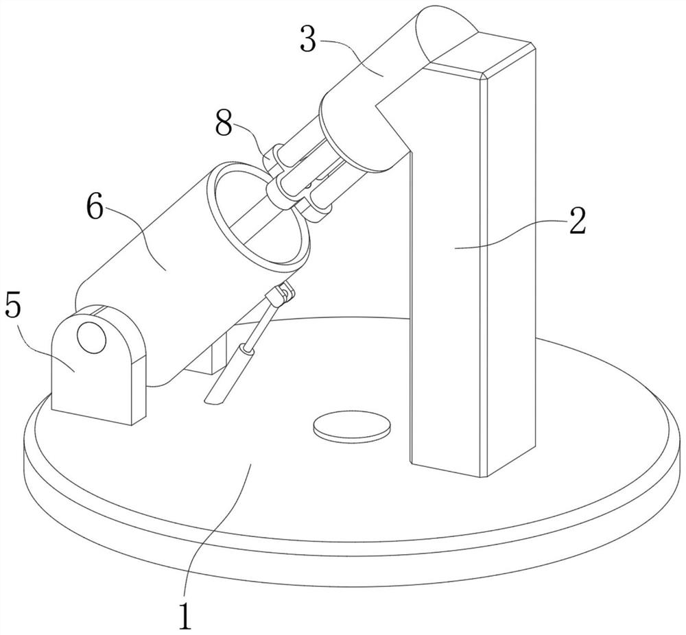
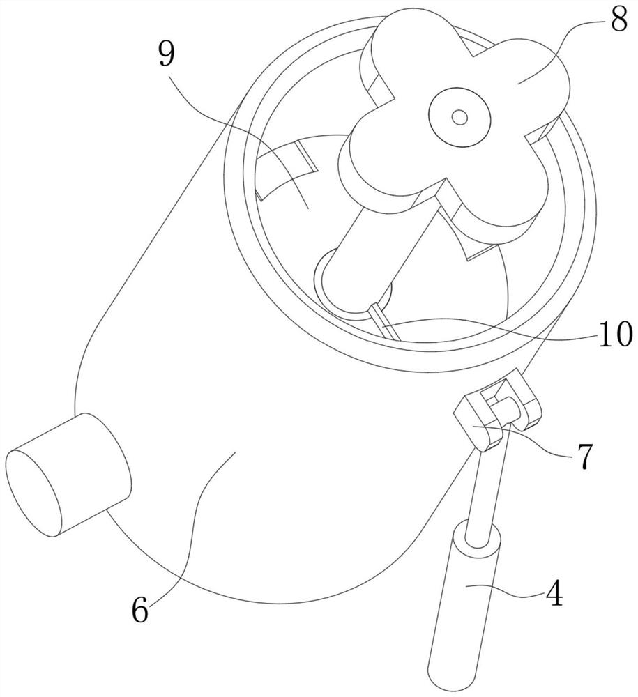
[0029] see Figure 1-Figure 2, a solid-liquid separation device 9 for petroleum refining and chemical use in the figure, including a centrifugal base 1, a separation device 9 and a cleaning device 10, the centrifugal base 1 is fixedly connected with a device frame 2, and the device frame 2 is fixedly connected with a hydraulic pusher Rod 3, an electric telescopic rod 4 is fixedly connected to the centrifugal base 1, an installation frame 5 is fixedly connected to the centrifugal base 1, a cylinder 6 is rotatably connected to the installation frame 5, and the cylinder 6 is fixedly connected to the electric telescopic rod 4. The output end is rotatably connected to the fixed block 7, the output end of the hydraulic push rod 3 is fixedly connected with a connecting block 8, the separation device 9 is installed on the connecting block 8, and is used to extract the oil that has been stratified after centrifugation. The cleaning device 10 is installed in the The separation device 9 ...

Embodiment 2

[0034] see Figure 7-Figure 10 The second embodiment will be described. This embodiment will further describe the first embodiment. The linkage 16 in the figure includes a first spring 18 fixedly installed in the separation groove 13. The first spring 18 is fixedly connected with the stopper 14 and pushes the rod. The bottom end of 11 is fixedly connected with a pulling block 19 which is slidably connected with the device slot 15. A guide groove 20 is opened on the push plate 12, and a first pull rope 21 is slidably connected in the guide groove 20. One end of the first pull rope 21 is connected to the stopper. The block 14 is fixedly connected, and the other end is fixedly connected to the pulling block 19 , a fixing rod 22 is fixedly connected in the device slot 15 , and a fixing plate 23 is fixedly connected to the bottom end of the fixing rod 22 .

[0035] see Figure 4-Figure 6 , the balance piece 17 in the figure includes a fixing ring 24, the push rod 11 is provided wi...

Embodiment 3

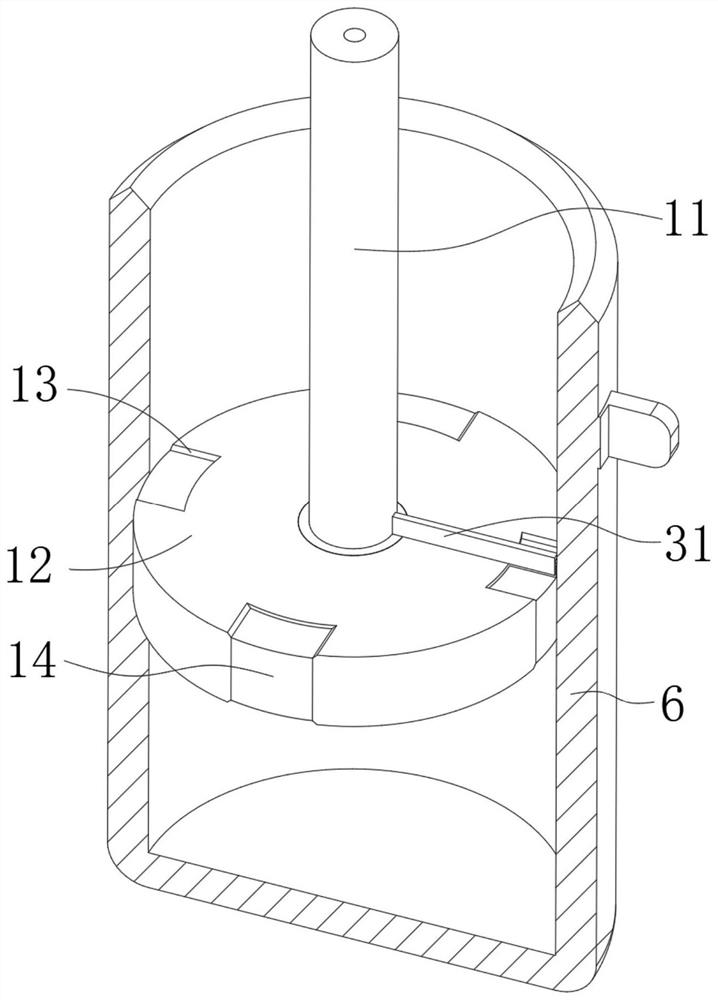
[0039] see Figure 4-Figure 6 Embodiment 3 will be described. This embodiment will further describe Embodiment 1. The cleaning device 10 in the figure includes a rotating ring 30 that is rotatably connected to the device groove 15. The rotating ring 30 is fixedly connected with a sliding connection with the upper surface of the push plate 12. The cleaning rod 31, the cleaning rod 31 is provided with a cleaning member 32 for cleaning the depressions on the push plate 12, and the device groove 15 is provided with a rotating ring 30 for rotating when the push rod 11 is pulled, and when the push rod 11 is pushed The moment when the disk 12 is separated from the inner wall of the cylinder 6, the driving member 33 for scraping the oil on the upper surface of the disk 12 is pushed.

[0040] see Figure 7-Figure 10 , the driving member 33 in the figure includes a clockwork spring 34 fixedly installed in the device slot 15, one end of the clockwork spring 34 is fixedly connected with ...


PUM


Abstract

The invention discloses a solid-liquid separation device for petroleum refining, relates to the field of solid-liquid separation for petroleum refining, and solves the problem that when an existing solid-liquid separation device for petroleum refining is used, petroleum is easy to adhere to the surface of a filter screen, so that the filtering speed is greatly reduced after long-time use, and the separation efficiency is influenced. Comprising a centrifugal base, a separation device and a cleaning device, a device frame is fixedly connected to the centrifugal base, a hydraulic push rod is fixedly connected to the device frame, a mounting frame is fixedly connected to the centrifugal base, a cylinder is rotationally connected to the mounting frame, and a connecting block is fixedly connected to the output end of the hydraulic push rod. By arranging the separation device and the cleaning device, when the separation device moves downwards, petroleum gradually flows to the position above the separation device, when the separation device moves upwards, the opening is closed, so that the petroleum above the separation device is pushed out, and when the separation device completely pushes out the petroleum in the barrel, the cleaning device is linked to rapidly scrape the petroleum on the surface of the separation device.

Description

technical field [0001] The invention relates to the technical field of solid-liquid separation for petroleum refining, in particular to a solid-liquid separation device for petroleum refining. Background technique [0002] Petroleum is a viscous, dark brown liquid known as the "blood of industry." There are petroleum reserves in some areas in the upper crust of the earth. The main components are mixtures of various alkanes, naphthenes and aromatic hydrocarbons, which are one of the main objects of geological exploration. The solid impurities are removed, and then the next step of refining is carried out. [0003] The existing Chinese patent CN112495041A discloses a solid-liquid separation device for petroleum refining. In this application, the oil mixture is centrifugally treated by the principle of centrifugal force through the filter screen cylinder, the oil outlet and the receiving shell, so that the liquid oil is Under the action of centrifugal force, it penetrates thr...

Claims


Application Information

Patent Timeline
Patent Type & Authority Applications(China)
IPC IPC(8): B04B1/00B04B11/04B04B15/06C10G31/10
CPCB04B1/00B04B11/04B04B15/06C10G31/10
Inventor 张霄逸邱燕云柳忠
Owner 张霄逸
Why Eureka
Try Eureka