Automatic collection device for laboratory chemical sewage
A technology for automatic collection of chemical sewage, applied to chemical instruments and methods, cleaning methods and utensils, smoke and dust removal, etc., can solve problems such as endangering human health, residual chemical sewage, easy spillage of chemical sewage, etc., to avoid leakage and easy to use Effect
- Summary
- Abstract
- Description
- Claims
- Application Information
AI Technical Summary
Problems solved by technology
Method used
Image
Examples
Embodiment 1
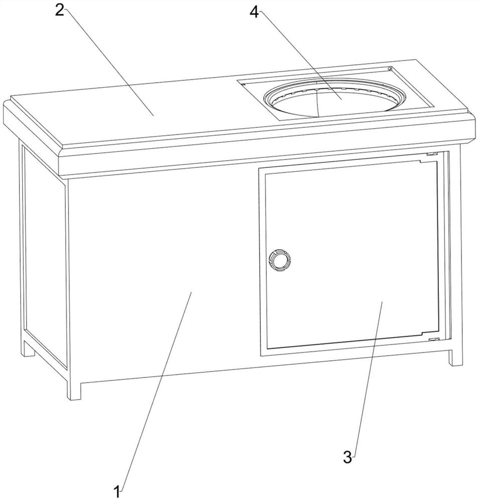
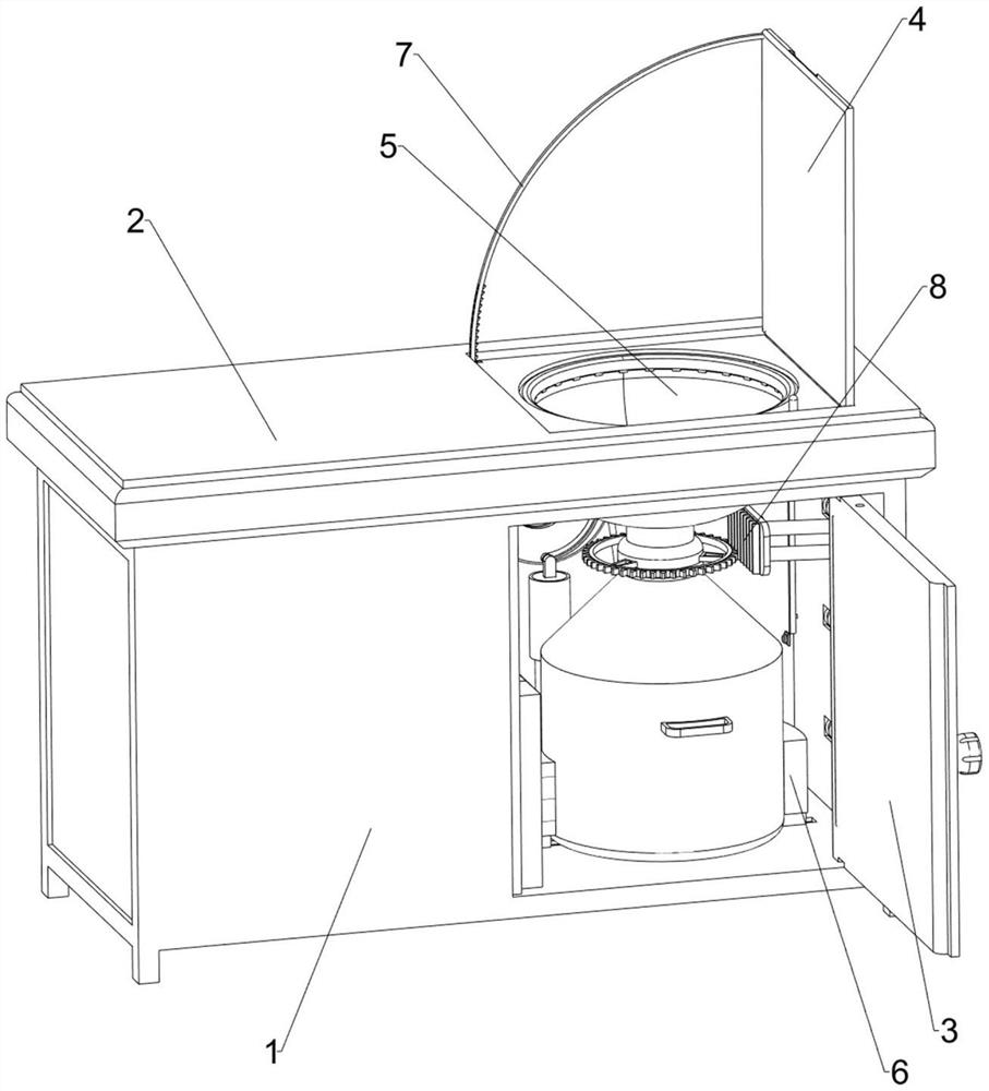
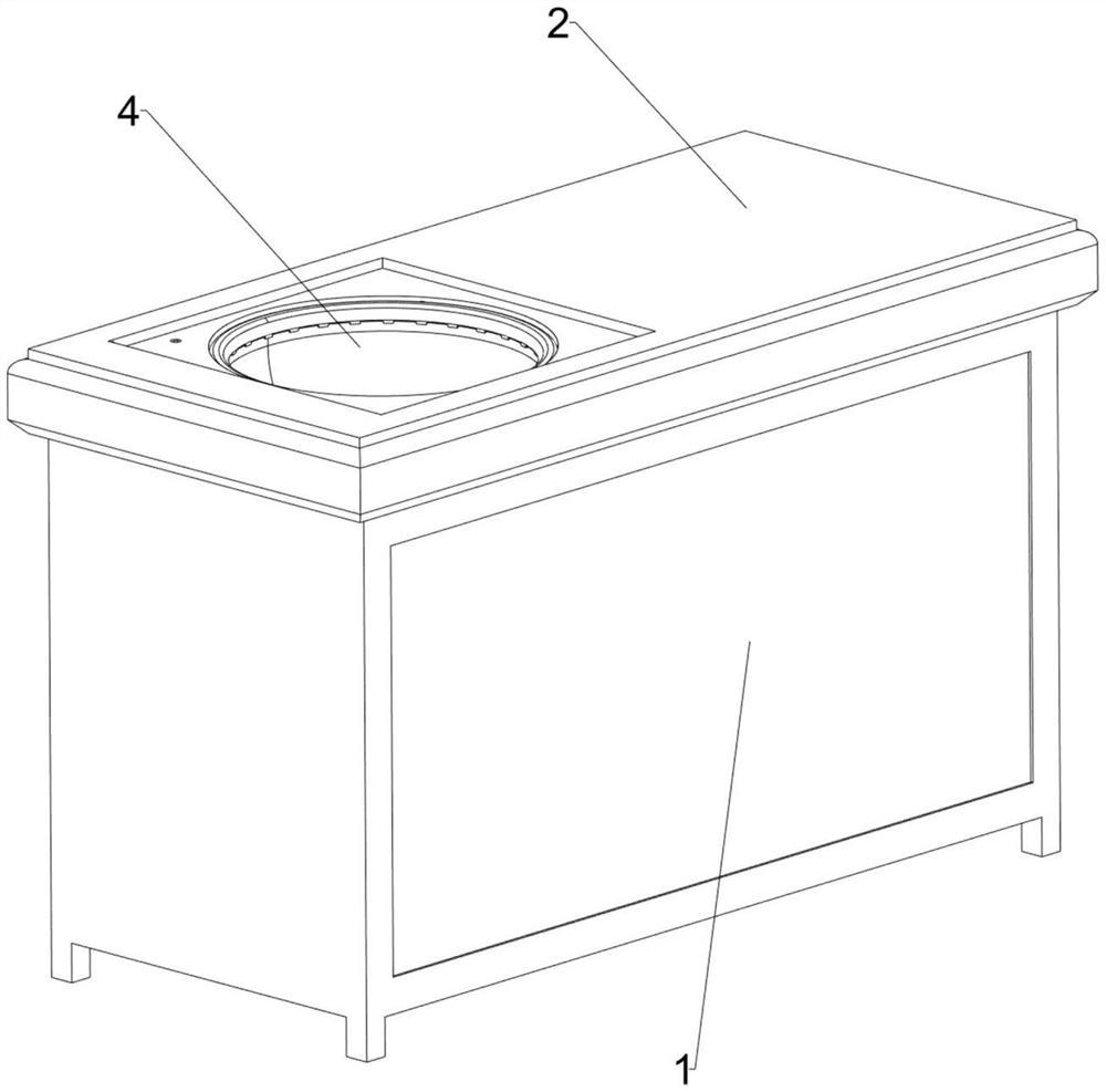
[0036] An automatic collection device for laboratory chemical sewage, such as Figure 1-11 As shown, it includes a cabinet body 1, a table board 2, a cabinet door 3, a cover plate 4, a sewage collection device 5 and a positioning device 6. The top of the cabinet body 1 is welded with a table board 2, and the right front side of the cabinet body 1 is installed through a hinge. The cabinet door 3, the right top of the table board 2 is installed with a cover plate 4 through hinges, the right part of the cabinet body 1 is provided with a sewage collection device 5 for collecting laboratory chemical sewage, and the inner bottom of the cabinet body 1 is provided with a sewage collection device 5. Positioning device 6.
[0037] The sewage collection device 5 includes a collection basin 53, a roller 54, a rubber ring 55, a first spring 56 and a collection bucket 57. A round opening 51 is opened on the right side of the table 2, and the round opening 51 is located under the cover plate...
Embodiment 2
[0041] On the basis of Example 1, as Figure 9-16 As shown, a flushing device 7 is also included. The flushing device 7 includes a rotating shaft 71, a ratchet wheel 72, a spiral groove disc 73, a torsion spring 74, an arc-shaped ratchet bar 75, a water tank 76, a water inlet hard pipe 77, a cylinder 78, a piston The rod 781, the second spring 782, the hose 79, the annular water outlet pipe 710, the L-shaped clamping rod 711 and the third spring 712, a rotating shaft 71 is rotatably installed in the middle of the inner rear side of the cabinet 1, and the middle of the rotating shaft 71 is connected by a key The ratchet wheel 72 is installed in the way, the front end of the rotating shaft 71 is welded with a spiral groove plate 73, a torsion spring 74 is arranged between the spiral groove plate 73 and the inner rear side of the cabinet 1, one end of the torsion spring 74 is connected with the rear side of the spiral groove plate 73, and the other end It is connected with the in...
Embodiment 3
[0046] On the basis of Example 2, as Figure 12-15 As shown, it also includes a lock rod 10 and a fifth spring 11, a cavity 9 is opened on the right front of the cover plate 4, a lock rod 10 is slidably arranged in the cavity 9, and a first lock rod 10 is connected with the cavity 9. The five springs 11 and the fifth spring 11 are in a compressed state. The top right side of the cabinet door 3 has a card hole 12 .
[0047] It also includes a first magnet block 13 and a second magnet block 14, a first magnet block 13 is fixedly installed at the lower end of the arc-shaped ratchet bar 75, a second magnet block 14 is installed on the rear side of the inner top of the cabinet 1, and the first magnet block 13 Adsorbing and matching with the second magnet block 14 .
[0048] A rubber sleeve 15 is also included. The handle of the cabinet door 3 is sleeved with the rubber sleeve 15, and the rubber sleeve 15 is used to increase the frictional force.
[0049] When the cover plate 4 is...
PUM
 Abstract
Description
Claims
Application Information
 - R&D
- Intellectual Property
- Life Sciences
- Materials
- Tech Scout
- Unparalleled Data Quality
- Higher Quality Content
- 60% Fewer Hallucinations
Browse by: Latest US Patents, China's latest patents, Technical Efficacy Thesaurus, Application Domain, Technology Topic, Popular Technical Reports.
© 2025 PatSnap. All rights reserved.Legal|Privacy policy|Modern Slavery Act Transparency Statement|Sitemap|About US| Contact US: help@patsnap.com


