
Wafer marking equipment

A technology for marking equipment and wafers, which is applied in welding equipment, metal processing equipment, laser welding equipment, etc.

Pending Publication Date: 2022-07-22
SHENZHEN TETE SEMICON EQUIP CO LTD
View PDF0 Cites 0 Cited by
  • Summary
  • Abstract
  • Description
  • Claims
  • Application Information

AI Technical Summary

Problems solved by technology

Since the loading of the material box is manually placed, this method is likely to cause errors in the placement position of the material box, which will affect the efficiency of marking

Method used


Image

  • Wafer marking equipment
  • Wafer marking equipment
  • Wafer marking equipment

Examples


Embodiment Construction

[0038] The technical solutions in the embodiments of the present invention will be clearly and completely described below with reference to the accompanying drawings in the embodiments of the present invention. Obviously, the described embodiments are only a part of the embodiments of the present invention, but not all of the embodiments. Based on the embodiments of the present invention, all other embodiments obtained by those of ordinary skill in the art without creative efforts shall fall within the protection scope of the present invention.

[0039] It should be noted that all directional indications (such as up, down, left, right, front, back, etc.) in the embodiments of the present invention are only used to explain the relationship between various components under a certain posture (as shown in the accompanying drawings). The relative positional relationship, the movement situation, etc., if the specific posture changes, the directional indication also changes accordingl...


PUM


Abstract

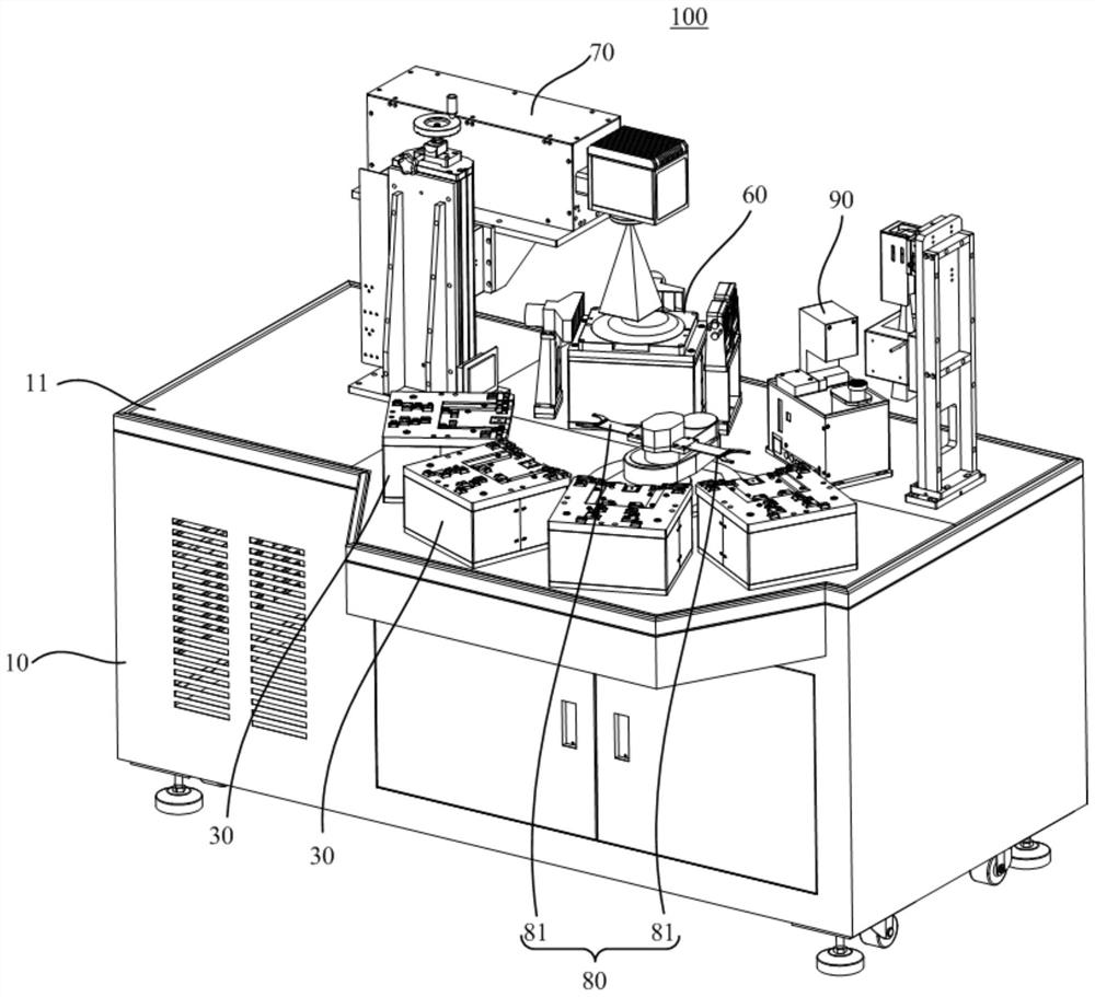
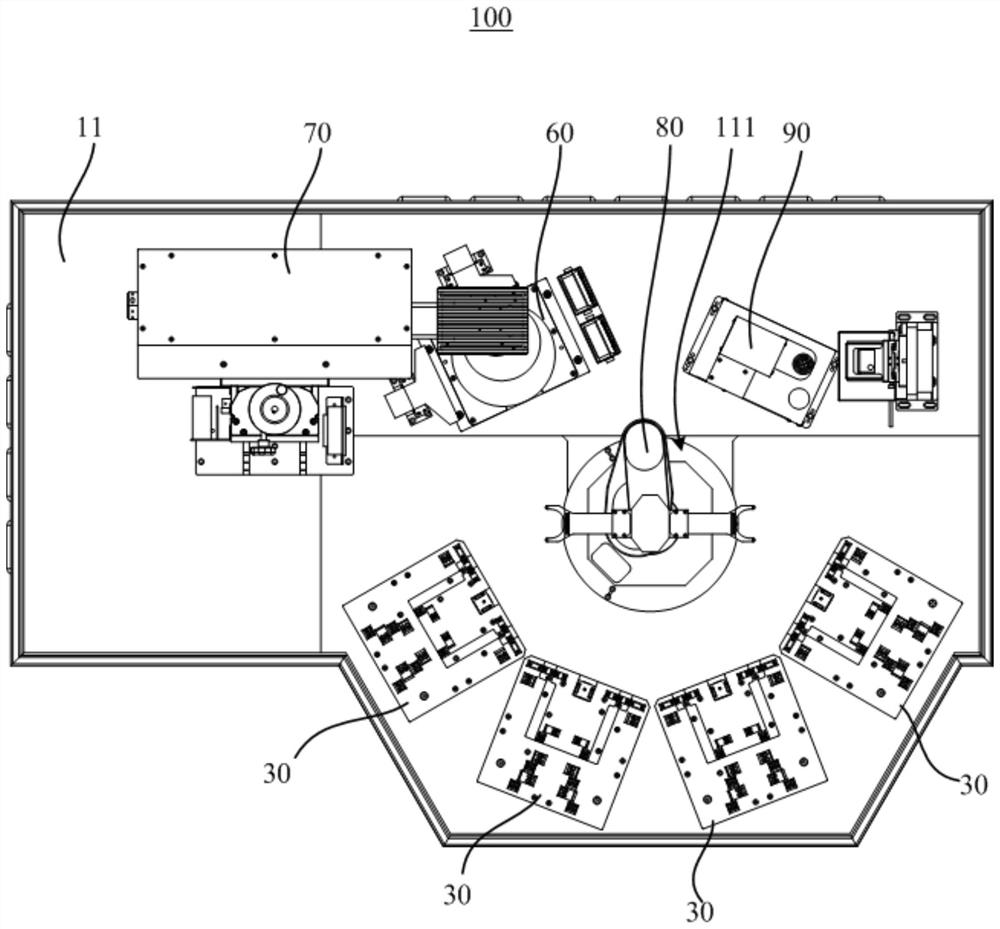
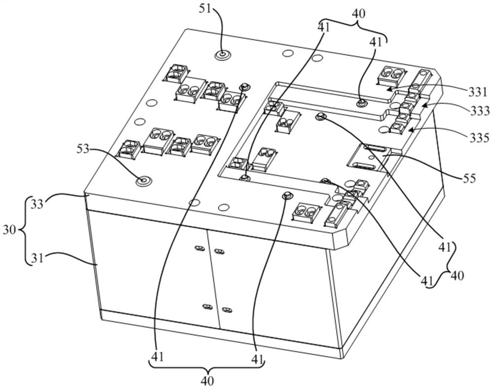
The invention discloses wafer marking equipment, which comprises a rack, at least one material box carrier and at least one detection mechanism, and is characterized in that the rack is provided with a machine table; the material box carrier is arranged on the machine table, and the material box carrier is used for fixing a wafer material box; the detection mechanism comprises at least two detectors, the at least two detectors are arranged on the surface of the material box carrier at intervals, and when the two detectors detect signals of the wafer material boxes at the same time, the wafer material boxes are preassembled in place. According to the technical scheme, the feeding error of the material box is reduced, and the wafer marking efficiency is improved.

Description

technical field [0001] The present invention relates to the technical field of laser equipment, in particular to a wafer marking equipment. Background technique [0002] Silicon carbide (SiC), also called silicon wafer, is an important raw material for silicon semiconductor circuits. With the wide application and development of wafers, wafer processing manufacturers usually achieve quality tracking and traceability of wafer products by marking and opening the wafers. In the related art, the whole box of wafers is manually placed on the preset position of the wafer marking equipment, and then the wafers to be marked are sequentially taken out from the material box by a material-moving manipulator and placed on the processing position for processing. After the processing is completed, the wafers are put into the material box in turn. Since the feeding of the material box is manually placed, this method is easy to cause errors in the placement position of the material box, wh...

Claims


Application Information

Patent Timeline
Patent Type & Authority Applications(China)
IPC IPC(8): B23K26/362B23K26/70
CPCB23K26/362B23K26/702B23K2103/56B23K2101/007
Inventor 李志强李文强杨建新朱霆盛辉周学慧张凯
Owner SHENZHEN TETE SEMICON EQUIP CO LTD
Learn More