
Novel injection molding machine

An injection molding machine and a new type of technology, applied in the field of injection molding machines, can solve the problems of melting plastic particles, blockage of hoppers, and poor cooling effect of cooling water, and achieve the effects of accelerating heat dissipation and cooling, good recycling, and good cooling effect.

Pending Publication Date: 2022-07-22
苏州市百诺精密科技股份有限公司
View PDF0 Cites 0 Cited by
  • Summary
  • Abstract
  • Description
  • Claims
  • Application Information

AI Technical Summary

Problems solved by technology

[0002] Injection molding machine is a device that makes thermoplastics into plastic products through molds. The hopper of the injection molding machine is installed on the barrel, and a heating ring is installed outside the barrel. When the injection molding machine is working, the temperature at the channel of the hopper is high, which is easy to use. The plastic particles flowing into the hopper melt and form lumps, causing the blockage of the hopper and affecting the normal operation of the injection molding machine. Therefore, it is necessary to cool down the side wall of the hopper to avoid blockage of the hopper
[0003] In the prior art, the cooling water pipe is wound outside the hopper, and the hopper is cooled by cooling water. The cooling water in the pipe cools the hopper and then flows back to the water tank, and then cools the cooling water in the water tank through the cooling fins to achieve cooling. The recycling of water, but the heat sink has a poor cooling effect on the cooling water in the water tank, which affects the recycling of cooling water

Method used


Image

  • Novel injection molding machine
  • Novel injection molding machine
  • Novel injection molding machine

Examples


Embodiment Construction

[0036] The present invention will be further described in detail below with reference to the accompanying drawings. Wherein the same parts are denoted by the same reference numerals. It should be noted that the words "front", "rear", "left", "right", "top", "bottom", "bottom" and "top" used in the following description refer to the Orientation, the words "inner" and "outer" refer to directions toward or away from the geometric center of a particular component, respectively.

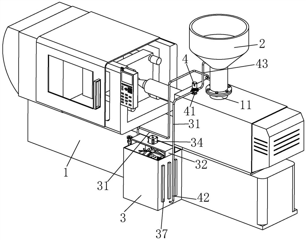
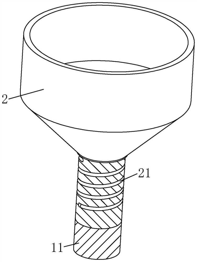
[0037] The invention discloses a novel injection molding machine, such as figure 1 and figure 2 As shown, it includes an injection molding machine body 1; a hopper 2 is detachably installed on the top of the injection molding machine body 1, and a water tank 3 is fixed on the side wall of the injection molding machine body 1; There is a cooling channel 21 inside the wall; the cooling channel 21 is spiral; the injection molding machine body 1 is provided with a conveying mechanism 4 for conveying cooli...


PUM


Abstract

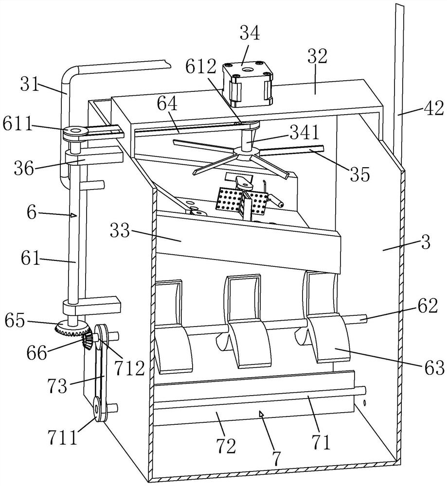
The invention relates to the technical field of injection molding machines, and particularly discloses a novel injection molding machine which comprises an injection molding machine body. A hopper is detachably mounted at the top of the injection molding machine body; a water tank is fixedly connected to the side wall of the injection molding machine body; a cooling channel is arranged in the side wall of the hopper; a conveying mechanism for conveying cooling water is arranged on the injection molding machine body; a return pipe is fixedly connected to the outer side wall of the water tank; the return pipe is communicated with an outlet of the cooling channel; a motor is mounted at the top of the water tank; the output end of the motor is fixedly connected with a first rotating shaft; fan blades are fixedly connected to the end part of the first rotating shaft; a concave plate is fixedly connected to the inner side wall, on the same side as the backflow pipe, of the water tank. A shunting mechanism for shunting cooling water is arranged in the concave plate; an outlet of the return pipe is opposite to the concave plate; and backflow cooling water is subjected to air cooling through rotation of the fan blades, heat dissipation of the cooling water is further promoted through the flow dividing mechanism, and therefore the cooling water can be better recycled.

Description

technical field [0001] The invention relates to the technical field of injection molding machines, in particular to a novel injection molding machine. Background technique [0002] The injection molding machine is a device that makes thermoplastic plastics into plastic products through a mold. The hopper of the injection molding machine is installed on the barrel, and a heating ring is arranged outside the barrel. The plastic particles flowing into the hopper melt into a block, causing the hopper to block and affecting the normal operation of the injection molding machine. Therefore, it is necessary to cool down the side wall of the hopper to avoid blockage of the hopper. [0003] In the prior art, most of the cooling water pipes are wrapped around the outside of the hopper, and the hopper is cooled by the cooling water. The cooling water in the pipe cools the hopper and returns to the water tank, and then the cooling water in the water tank is cooled by the heat sink to ach...

Claims


Application Information

Patent Timeline
IPC IPC(8): B29C45/72
CPCB29C45/72
Inventor 郑先祥刘万悦万兵
Owner 苏州市百诺精密科技股份有限公司
Learn More