Networked traction power supply system and source network vehicle storage cooperative power supply method

A traction power supply system, traction power supply technology, applied in power lines, vehicle components, transportation and packaging, etc., can solve the problems of insufficient use of electric energy, single energy structure, low energy utilization rate, etc., to reduce the loss of traction network, change Single energy structure and the effect of avoiding system loss

Active Publication Date: 2022-07-22
CHINA RAILWAY DESIGN GRP CO LTD
View PDF5 Cites 0 Cited by
  • Summary
  • Abstract
  • Description
  • Claims
  • Application Information

AI Technical Summary

Problems solved by technology

In order to reduce the negative-sequence impact caused by the three-phase-single-phase asymmetric transformation, the traction transformers generally rotate the phase sequence to connect to the power system, that is, the catenary supplied by different traction transformers adopts different phases of the power system, and the catenary of different phases is connected to the power system. It is necessary to set up electrical phase separation, which leads to the formation of a unitized power supply pattern in the traction power supply system, and the electric energy regenerated when the train brakes cannot be fully utilized in the system
my country's existing traction power supply system has a single energy structure and low energy utilization rate. Under the "double carbon" goal, it is urgent to promote technological innovation in the process of green and low-carbon transformation

Method used


Image

  • Networked traction power supply system and source network vehicle storage cooperative power supply method
  • Networked traction power supply system and source network vehicle storage cooperative power supply method
  • Networked traction power supply system and source network vehicle storage cooperative power supply method

Examples


Embodiment 1

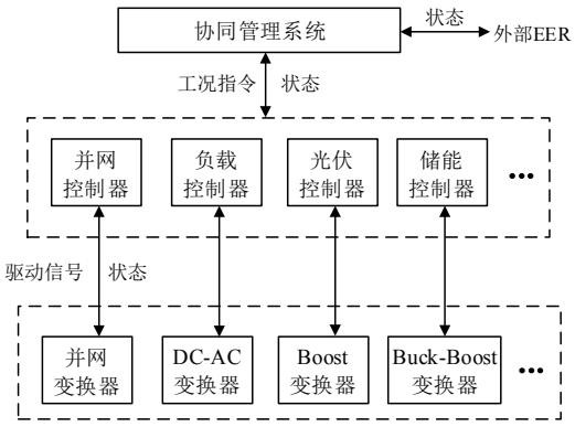
[0069] The networked traction power supply system of this embodiment includes a traction power supply station, and the traction power supply station is provided with a collaborative management system, a plurality of network controllers, and a plurality of port converters corresponding to the network controllers respectively;

[0070] The collaborative management system is used for sharing overall status information with adjacent traction power supply stations, receiving data information sent by the network controller, or sending working condition instructions to the network controller;

[0071] The network controller is used to receive the state information of the port converter and send the driving signal at the same time;

[0072] The port converter is used to receive the drive signal of the network controller, so as to complete the coordinated power supply of the source, network, vehicle and storage.

[0073] The network controller includes a grid-connected controller, a lo...

Embodiment 2

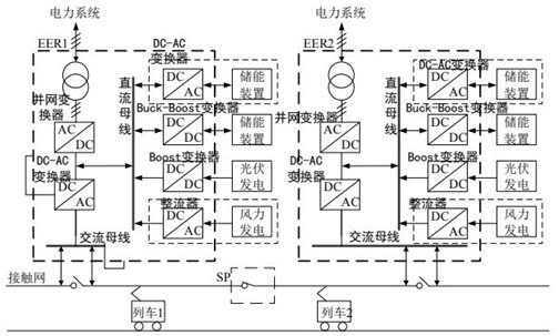
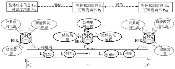
[0119] The networked traction power supply system refers to a new generation of traction power supply system that can realize power integration between adjacent traction power supply stations, coordinated power supply for trains by groups of traction power supply stations, renewable energy access, and electrical energy storage and power supply. Typical topologies such as figure 1 As shown in the figure, the number of connected devices on the DC bus side can be selected flexibly according to the actual situation. In order to realize the coordinated power supply of the source, network, vehicle and storage, at least one new energy power generation device and one energy storage device should be included;

[0120] It should be noted that this embodiment does not limit the topology of the networked traction power supply system, but to simplify the description, the method is described according to the topology of connecting one photovoltaic power generation device and one energy stora...

Embodiment 3

[0129] As an example, in this embodiment, the implementation process of the source-network vehicle-storage coordinated power supply of the networked traction power supply system is as follows:

[0130] The state of the networked traction power supply system at a certain moment is as follows: Figure 5 As shown, the EER power supply range is [0+000, 110+000], and the remaining capacity of the energy storage device is S SOC =70%SN, rated charge and discharge power P SC =P SD =5MW, photovoltaic power: P E =7.5MW, the source-network vehicle-storage coordination process is as follows:

[0131] Since Ka≤l1N ≤S SOC ≤90%S N , the energy storage controller determines that the energy storage device can participate in power coordination in both directions, and the energy storage state information is "11".

[0132] The collaborative management system integrates the train state information and the energy storage state information to obtain the overall state parameter "111". The comma...


PUM


Abstract

The invention relates to a networked traction power supply system and a source network train storage cooperative power supply method using the system, comprising the following steps: acquiring the position of each train, and comparing the position with the power supply position range of a traction power supply station to form train state information; obtaining the residual capacity of the energy storage device, and comparing the residual capacity with the rated capacity of the energy storage device to form energy storage state information; according to the train state information and the energy storage state information, energy collaboration in the traction power supply station is carried out, and overall state information under different train and energy storage states and schedulable power of the traction power supply station are obtained; acquiring train state information, energy storage state information and schedulable power of adjacent traction power supply stations, matching the train state information, the energy storage state information and the schedulable power with the adjacent traction power supply stations, realizing inter-station energy scheduling between the traction power supply stations if matching succeeds, and not participating in inter-station energy scheduling by the traction power supply stations if matching fails; according to the invention, renewable energy can be consumed on site, and the traction network loss is reduced.

Description

technical field [0001] The invention belongs to the field of traction power supply systems, and in particular relates to a networked traction power supply system and a source-network-vehicle-storage coordinated power supply method. Background technique [0002] The traction power supply system of my country's electrified railways draws power from the public power grid, and is then stepped down by a traction transformer and then sent to the catenary. In order to reduce the negative sequence effect caused by the three-phase-single-phase asymmetric transformation, the traction transformers are generally connected to the power system in rotation, that is, the catenary power supply of different traction transformers adopts different phases of the power system, and the catenary of different phases is connected to the power system. Electric phase separation needs to be set up, which leads to the formation of a unitized power supply pattern in the traction power supply system, and t...

Claims


Application Information

Patent Timeline
Patent Type & Authority Applications(China)
IPC IPC(8): B60M3/00
CPCB60M3/00
Inventor 尚国旭董志杰魏建忠李波杨振龙杨嘉琛林晨张宇许永坚郭晓旭马志远杜瑞建邢晓乾庄德举刘聪邵明黄海浪曲衍宁
Owner CHINA RAILWAY DESIGN GRP CO LTD
Why Eureka
Try Eureka