Lifting mechanism for hanging and conveying pouring barrel

A hanging and No. 1 technology, applied in the field of hanging conveyor lines, can solve problems such as pouring barrel shaking, and achieve the effect of ensuring stability

Pending Publication Date: 2022-07-22
安徽省天鑫内燃机配件有限公司
View PDF0 Cites 0 Cited by
  • Summary
  • Abstract
  • Description
  • Claims
  • Application Information

AI Technical Summary

Problems solved by technology

[0005] In order to make up for the shortcomings of the existing technology and solve the problem that the pouring barrel may shake during the process of hoisting or walking on the hanging assembly line, the invention provides a lifting mechanism for hanging and conveying the pouring barrel

Method used


Image

  • Lifting mechanism for hanging and conveying pouring barrel
  • Lifting mechanism for hanging and conveying pouring barrel
  • Lifting mechanism for hanging and conveying pouring barrel

Examples


specific Embodiment approach

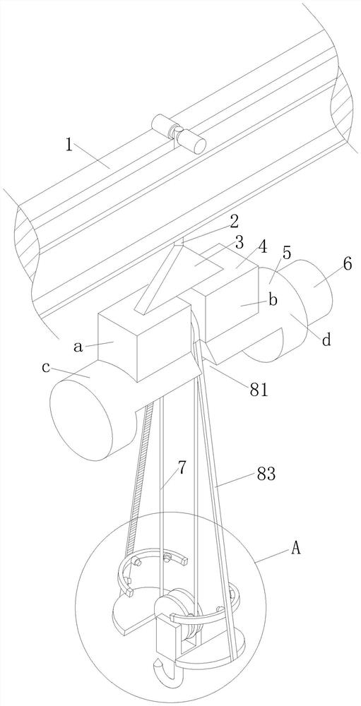
[0050] As a specific embodiment of the present invention, the stabilization mechanism 8 includes:

[0051] A turntable 82, the turntable 82 is located in the cavity 81 and is rotatably connected to the side wall of the control box 4, and the turntable 82 is two;

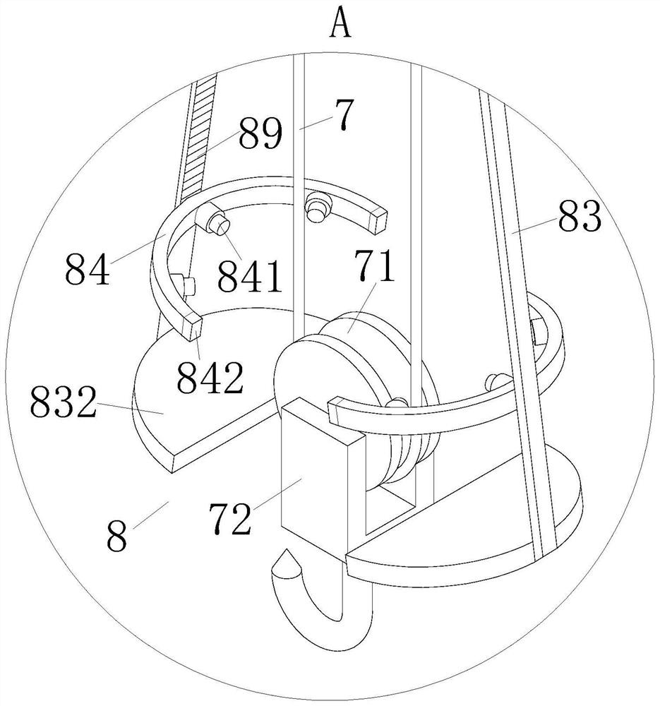
[0052] Clamping rods 83, the clamping rods 83 are two and both pass through the turntable 82 and are slidably connected to the turntable 82;

[0053] There are two clamping frames 84 , and both of the clamping frames 84 are fixedly connected to the position of the clamping rod 83 near the bottom.

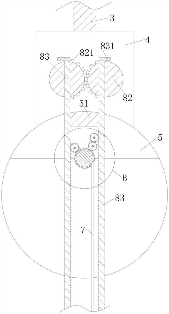
[0054] As a specific embodiment of the present invention, the turntable 82 is provided with latching teeth 821 on the side wall of the control box 4 that is close to and adjacent to the turntable 82, and the latching teeth 821 are engaged with each other; the control A drive motor is fixed inside the box 4 , and one of the turntables 82 is fixedly connected to the output shaft of the drive motor.

[0055] During operatio...

Embodiment approach

[0057] As a specific embodiment of the present invention, the No. 2 gear 86 , the No. 3 gear 87 and the No. 4 gear 88 have the same specifications and sizes, and the diameter of the index circle of the No. 1 gear 85 is the same as that of the No. 2 gear 86 , the No. The diameter of the index circle of the gear 87 and the fourth gear 88 is four times, and the number of teeth of the first gear 85 is twice that of the second gear 86 , the third gear 87 and the fourth gear 88 .

[0058] During operation, when the turntable 82 drives the clamping rod 83 and the clamping frame 84 to clamp the pouring bucket, the clamping rod 83 is just in a vertical state, and the racks 89 on the two clamping rods 83 are respectively It meshes with the No. 2 gear 86 and the No. 4 gear 88. When the winding shaft 61 rotates counterclockwise to lift the pouring barrel, the No. 1 gear 85 coaxial with the winding shaft 61 rotates, and the No. 1 gear 85 drives the No. 2 gear 86 to rotate. The No. 2 gear 8...


PUM


Abstract

The invention belongs to the technical field of hanging conveying lines, and particularly relates to a lifting mechanism for hanging and conveying a pouring bucket. Comprising a sliding rail, a hanging rod, a connecting block, a control box, a first block, a first motor, a traction rope and a stabilizing mechanism. The clamping rod can be driven by the pouring barrel to ascend together, so that the clamping rod is matched with the clamping frame to clamp the pouring barrel in the lifting and transporting process of the pouring barrel, the clamping rod is of a rigid structure, and the clamping rod limits the relative displacement of the clamping rod, the control box and the first block in the rotating disc; therefore, the swinging of the pouring barrel in the lifting and transporting processes can be limited; and the stability of the pouring barrel in the lifting and transporting process is guaranteed.

Description

technical field [0001] The invention belongs to the technical field of hanging conveying lines, in particular to a lifting mechanism for hanging conveying of pouring buckets. Background technique [0002] Cylinder liner is the abbreviation of cylinder liner. It is embedded in the cylinder barrel of the cylinder block and forms the combustion chamber together with the piston and the cylinder head. The cylinder liner is divided into two categories: dry cylinder liner and wet cylinder liner. The cylinder liner whose back does not contact the cooling water is called a dry cylinder liner, and the cylinder liner whose back is in contact with the cooling water is a wet cylinder liner. The thickness of the dry cylinder liner is thin, the structure is simple, and the processing is convenient. The wet cylinder liner is in direct contact with the cooling water, so it is beneficial to the cooling of the engine and the small and lightweight engine; [0003] When the cylinder liner is p...

Claims


Application Information

Patent Timeline
IPC IPC(8): B66C1/34B66C13/06B66C11/16
CPCB66C1/34B66C13/06B66C11/16
Inventor 周茜
Owner 安徽省天鑫内燃机配件有限公司
Why Eureka
Try Eureka