Supercharge Your Innovation With Domain-Expert AI Agents!

Real-time cleaning and recycling system for fallen leaves on road surface

A recovery system and technology of fallen leaves, applied in the direction of road cleaning, grain processing, cleaning methods, etc., can solve the problems of low leaf recovery efficiency, difficult leaf recovery, and affecting efficiency, so as to facilitate transmission and aggregation, prevent dust from flying, and prevent self- Flappy effect

Inactive Publication Date: 2022-07-22
李怀
View PDF0 Cites 0 Cited by
  • Summary
  • Abstract
  • Description
  • Claims
  • Application Information

AI Technical Summary

Problems solved by technology

[0002] When cleaning the fallen leaves on the traditional pavement, whether it is manually cleaned by sanitation workers or cleaned by a sweeper, it will cause a lot of dust and cause a lot of pollution to the air environment
In addition, although the fallen leaves are not heavy, due to the gaps between the fallen leaves, the fallen leaves take up a lot of space when they are stacked. Once a large number of leaves fall on the road due to climatic factors, the recycling of these fallen leaves becomes a task. The problem is that people often see garbage sweepers transporting it back and forth many times before they can clean up the fallen leaves collected on a short section of road, resulting in low recycling efficiency of fallen leaves; not only that, no matter where the fallen leaves are dumped or It still takes up space, and the follow-up processing is still inconvenient
In addition, some leaves left on the trees are in a state of falling. It is likely that these leaves will fall after the road surface is cleaned, which makes it difficult to clean the road surface at one time and affects efficiency.

Method used


Image

  • Real-time cleaning and recycling system for fallen leaves on road surface
  • Real-time cleaning and recycling system for fallen leaves on road surface
  • Real-time cleaning and recycling system for fallen leaves on road surface

Examples


Embodiment Construction

[0026] The present invention will be described in further detail below with reference to the accompanying drawings and specific embodiments.

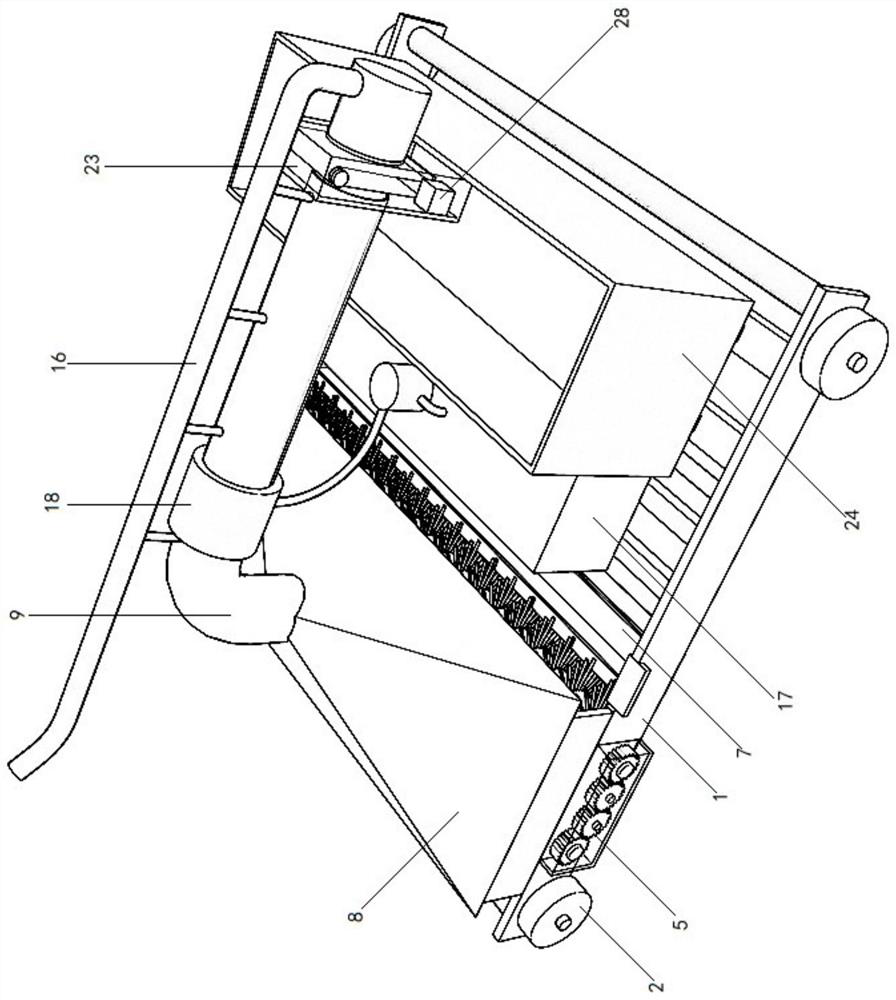
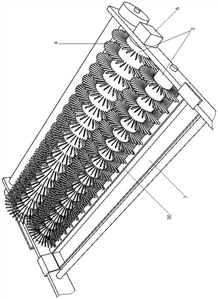
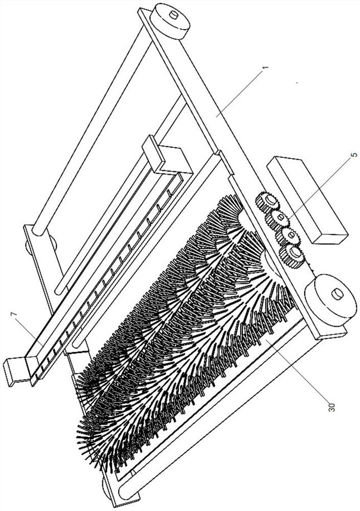
[0027] like Figure 1-3 As shown in the figure, the real-time cleaning and recycling system for road leaves includes a carrier frame 1 and wheels 2 installed on the carrier frame 1. The carrier frame 1 is sequentially provided with a leaf cleaning device, a crushing and conveying device, and a wetting and dust-reducing device from front to back. and a powder slag recovery device; the leaf cleaning device includes two cleaning rollers 3 arranged along the left and right directions; bristles 4 are evenly distributed on the cleaning roller 3; The left and right ends of the cleaning rollers 3 are respectively connected with the left and right sides of the carrying frame 1 for rotation correspondingly; a gear box 5 is installed between the left ends of the two cleaning rollers 3 for synchronous and reverse rotation of the two cleaning roller...


PUM


Abstract

The invention discloses an instant cleaning and recycling system for road surface fallen leaves, and relates to the technical field of road surface fallen leaf cleaning. The device comprises a bearing rack and wheels installed on the bearing rack, and the bearing rack is sequentially provided with a fallen leaf sweeping device, a smashing and conveying device, a wetting and dust falling device and a powder residue recycling device from front to back; the fallen leaf sweeping device comprises two sweeping rolling shafts arranged in the left-right direction. Bristles are uniformly distributed on the cleaning rolling shaft; the two cleaning rolling shafts are oppositely arranged in tandem; the left and right ends of the cleaning roller are correspondingly and rotationally connected with the left and right sides of the bearing rack respectively; a gear transmission box used for enabling the two sweeping rolling shafts to synchronously and reversely rotate is installed between the left ends of the two sweeping rolling shafts. The fallen leaf cleaning device has the beneficial effects that flying dust pollution generated during fallen leaf cleaning can be greatly reduced, the space occupied by fallen leaves during fallen leaf recycling can be greatly reduced, the cleaning efficiency is high, and the cleaning effect is good.

Description

technical field [0001] The invention relates to the technical field of road leaves cleaning. Background technique [0002] When the traditional leaves on the road are cleaned, whether it is manually cleaned by sanitation workers or cleaned by a sweeper, it will cause a large amount of dust and cause great pollution to the air environment. In addition, although the fallen leaves are not heavy, due to the gaps between the fallen leaves, the stacked leaves take up a lot of space. Once a large number of leaves fall to the road due to climatic factors, the recycling of these fallen leaves becomes an issue. The problem is that people often see garbage sweepers transporting back and forth many times to clean up the fallen leaves collected on a short section of road, resulting in low efficiency in recycling the fallen leaves; not only that, no matter where the collected leaves are dumped It still takes up space, and subsequent processing is still inconvenient. In addition, some of...

Claims


Application Information

Patent Timeline
IPC IPC(8): E01H1/08B01D46/681B01D46/10B01D50/60B02C18/00B02C18/14
CPCE01H1/0845B01D46/10B02C18/141B02C18/0084B02C2201/066
Inventor 李怀李杨曲理萍陈磊
Owner 李怀
Features
  • R&D
  • Intellectual Property
  • Life Sciences
  • Materials
  • Tech Scout
  • Unparalleled Data Quality
  • Higher Quality Content
  • 60% Fewer Hallucinations
Learn More