
Dust removal device for tunnel construction

A dust removal device and tunnel construction technology, which is applied in safety devices, dust prevention, mining equipment, etc., can solve the problems of high labor intensity, ineffective effect, and low dust removal efficiency, so as to ensure the overall construction progress, move quickly and conveniently, Wide coverage of dust removal effect

Pending Publication Date: 2022-07-22
NANTONG DAXIN ENG
View PDF0 Cites 0 Cited by
  • Summary
  • Abstract
  • Description
  • Claims
  • Application Information

AI Technical Summary

Problems solved by technology

The highest dust concentration often occurs after blasting on the face of the tunnel, which seriously affects the health of construction workers in the tunnel.
At present, the conventional method to deal with the dust concentration in tunnels is mainly to dilute the exhaust gas and reduce the dust concentration by blowing fresh air into the tunnel surface through the blower arranged on the left or right side of the tunnel, but the disposal process is long and the effect is not good. Obviously, it affects the next excavation construction of the tunnel, and ultimately affects the overall construction progress of the tunnel
Another way to deal with the dust concentration in the tunnel is to manually use high-pressure water guns to spray water to remove dust. This method has low dust removal efficiency and high labor intensity, which will also affect the overall construction progress of the tunnel.

Method used


Image

  • Dust removal device for tunnel construction
  • Dust removal device for tunnel construction
  • Dust removal device for tunnel construction

Examples


Embodiment 1

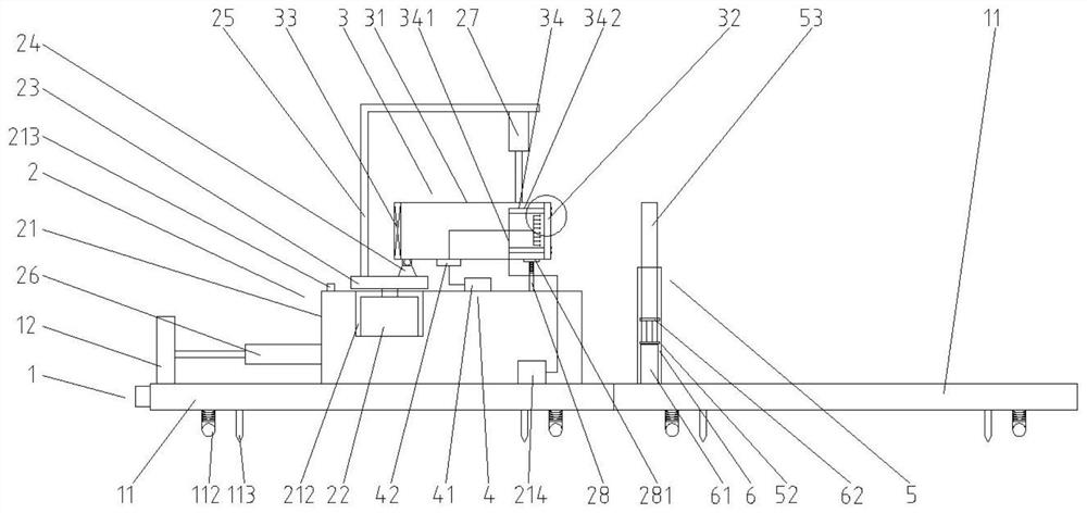
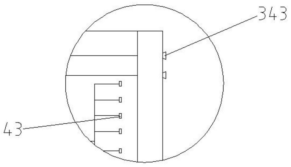
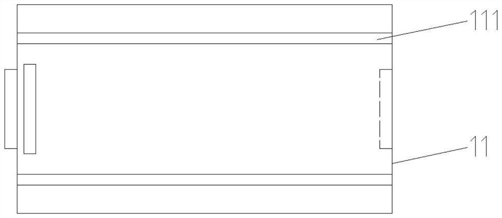
[0035] see Figure 1 to Figure 6 , this embodiment provides a dust removal device for tunnel construction, including a first support assembly 1, a second support assembly 2 and an air extraction and dust removal assembly 3;

[0036] The second support assembly 2 is disposed on the first support assembly 1, and the second support assembly 2 can slide left and right along the first support assembly 1;

[0037] The air extraction and dust removal assembly 3 is fixedly arranged on the second support assembly 2, and the air extraction and dust removal assembly is used for air extraction and dust removal in the tunnel.

[0038] see Figure 1 to Figure 6 , the first support assembly 1 includes a support plate 11 and a vertical plate 12; the support plates 11 are two and are inserted horizontally, and the upper end of the support plate 11 is provided along the longitudinal direction of the support plate 11. The chute 111; the vertical plate 12 is detachably inserted at the upper lef...

Embodiment 2

[0057] see Figure 7 to Figure 11 The difference between this embodiment and Embodiment 1 is that it also includes a water diversion assembly 7, the water diversion assembly 7 includes a first water diversion plate 71 and a second water diversion plate 72. A third slot (not shown) is arranged symmetrically at the ends, the first water diversion plate 71 is provided with a third plug that matches the third slot, and the second water diversion plate 72 is provided with a The fourth plug that is compatible with the first slot, the first water diversion plate 71 is two and is symmetrically plugged on the front and rear sides of one of the support plates 11, and the second water diversion plate 72 is plugged into the The right side of one of the support plates 11 .

[0058] When the first support assembly 1 is moved close to the tunnel face, the first water guide plate 71 and the second water guide plate 72 are plugged on the front and rear sides and the right end of the support p...


PUM


Abstract

The invention provides a dust removal device for tunnel construction. The dust removal device comprises a first supporting assembly, a second supporting assembly and an air draft dust removal assembly. The second supporting assembly is arranged on the first supporting assembly, and the second supporting assembly can slide left and right along the first supporting assembly; the air draft and dust removal assembly is fixedly arranged on the second supporting assembly and used for conducting air draft and dust removal on the tunnel. The dust removal coverage is wide, the dust removal efficiency is high, the overall construction progress of the tunnel is guaranteed, and meanwhile the working environment of workers is improved.

Description

technical field [0001] The invention belongs to the technical field of tunnel dust removal, in particular to a dust removal device for tunnel construction. Background technique [0002] When building road tunnels or railway tunnels in mountainous areas, single-headed tunnels are more common. In the process of tunnel excavation, the most important factor affecting the personal safety of construction personnel is the dust generated during the construction process, in addition to the sudden danger of the tunnel. The highest dust concentration often occurs after the blasting of the tunnel face, which seriously affects the health of the construction workers in the tunnel. At present, the conventional method of treating tunnel dust concentration is mainly to dilute the exhaust gas and reduce the dust concentration by blowing fresh air into the tunnel face through the air duct arranged on the left or right side of the tunnel, but the disposal process is long and the effect is not ...

Claims


Application Information

Patent Timeline
Patent Type & Authority Applications(China)
IPC IPC(8): E21F5/20E21F5/04
CPCE21F5/20E21F5/04
Inventor 孙国兵马和春
Owner NANTONG DAXIN ENG
Learn More