Continuous emission waste heat recovery equipment for boiler

A waste heat recovery equipment and continuous row technology, applied in heat exchange equipment, lighting and heating equipment, boiler cleaning devices, etc., can solve the problems of heat consumption, poor heat exchange effect, environmental pollution, etc., and achieve the effect of improving efficiency and quality

Pending Publication Date: 2022-07-22
河北邯峰发电有限责任公司
View PDF0 Cites 0 Cited by
  • Summary
  • Abstract
  • Description
  • Claims
  • Application Information

AI Technical Summary

Problems solved by technology

[0002] Industrial boiler products are divided into two types: steam or coal-fired. In order to ensure the water quality of the steam boiler, the boiler needs to be continuously discharged. Part of the sewage is directly discharged, which not only causes heat consumption, but also pollutes the environment, so various waste heat recovery devices have emerged
[0003] However, the existing waste heat recovery device for industrial boiler waste water has a complex structure, poor heat transfer effect, and low heat transfer efficiency, which affects heat transfer efficiency and waste heat utilization rate.

Method used


Image

  • Continuous emission waste heat recovery equipment for boiler
  • Continuous emission waste heat recovery equipment for boiler
  • Continuous emission waste heat recovery equipment for boiler

Examples


Embodiment Construction

[0024] The technical solutions in the embodiments of the present invention will be clearly and completely described below with reference to the accompanying drawings in the embodiments of the present invention. Obviously, the described embodiments are only a part of the embodiments of the present invention, but not all of the embodiments.

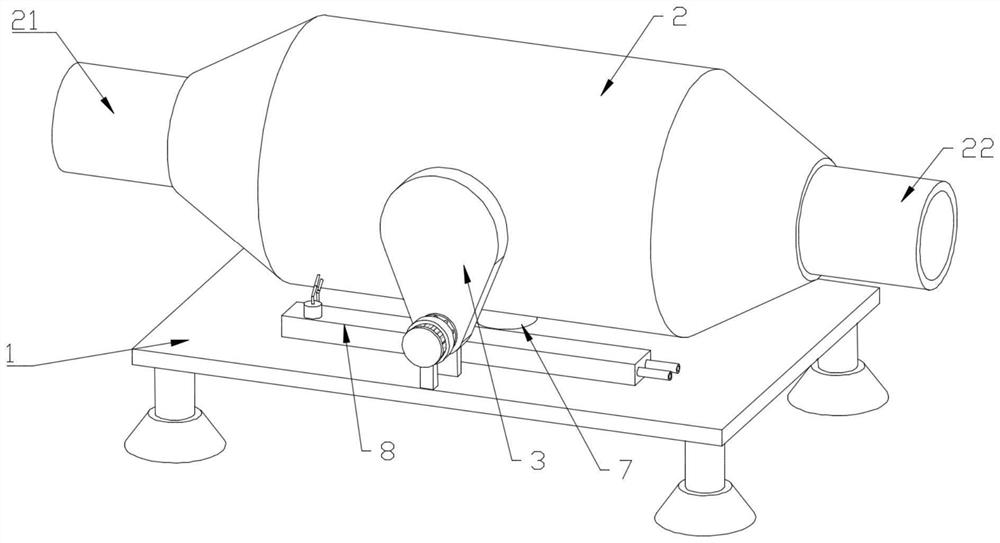
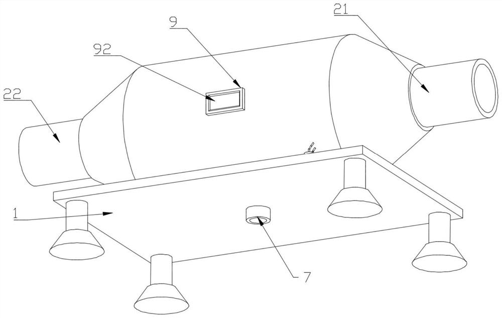
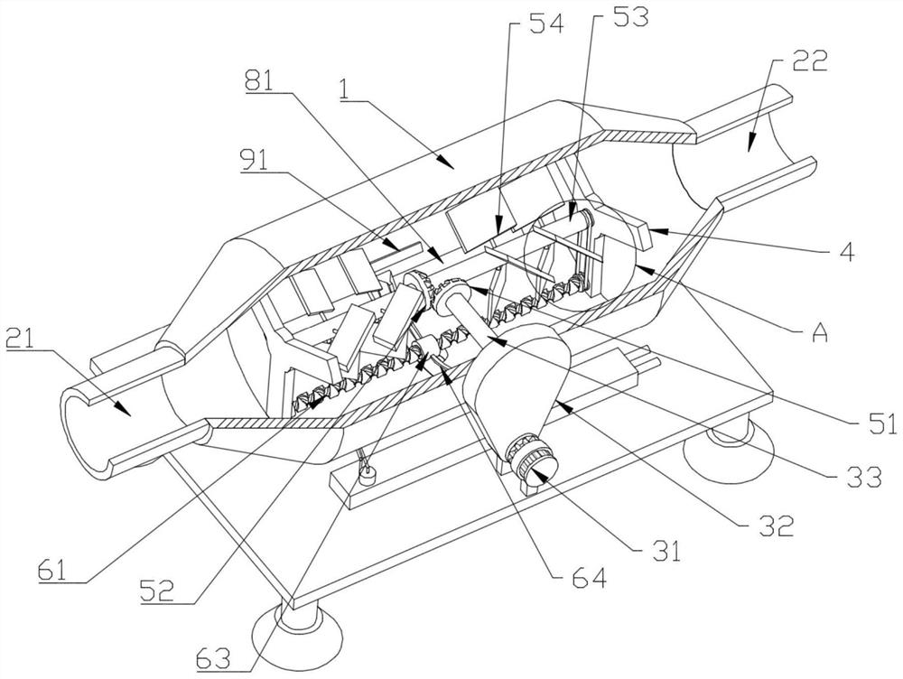
[0025] refer to Figure 1-6 , a boiler continuous row waste heat recovery equipment, comprising a base 1, a cylinder body 2 is fixedly connected to the middle of the upper end face of the base 1, a waste water inlet pipe 21 is fixedly connected to the left end face of the cylinder body 2, and a waste water outlet pipe is fixedly connected to the right end face of the cylinder body 2 22. The front part of the outer side wall of the cylinder body 2 is provided with a drive mechanism 3; the left and right sides of the inner cavity of the cylinder body 2 are fixedly connected with brackets 4, and a mixing mechanism 5 is arranged between the brac...


PUM


Abstract

The invention discloses boiler continuous emission waste heat recovery equipment, and relates to the technical field of waste heat recovery equipment, the boiler continuous emission waste heat recovery equipment comprises a base, the middle part of the upper end surface of the base is fixedly connected with a barrel, the left end surface of the barrel is fixedly connected with a wastewater inlet pipe, the right end surface of the barrel is fixedly connected with a wastewater outlet pipe, and the front part of the outer side wall of the barrel is provided with a driving mechanism; supports are fixedly connected to the left side and the right side of an inner cavity of the barrel, a mixing mechanism is arranged between the supports located on the left side and the right side, and heat exchange mechanisms are arranged on the front side and the rear side of the upper end face of the base. According to the heat exchange device, heat of high-temperature waste water in an inner cavity of the barrel can be absorbed through the arrangement of the heat exchange plate, heat exchange liquid in a liquid storage tank can enter the heat exchange coil through a liquid inlet pipe by fixedly connecting the heat exchange coil with the heat exchange plate and starting an output pump, then the heat exchange liquid is discharged from a liquid outlet pipe, circulation of the heat exchange liquid is achieved, and heat exchange efficiency is improved. Therefore, the whole device realizes the function of recycling the waste heat of the waste water.

Description

technical field [0001] The invention relates to the technical field of waste heat recovery equipment, in particular to a boiler continuous row waste heat recovery equipment. Background technique [0002] Industrial boiler products are divided into two types: steam or coal. In order to ensure the water quality of the steam boiler, the boiler needs to be continuously drained. The temperature of the drained water is the same as the saturated water temperature of the boiler. The blowdown consumes about 1% of the total energy. Part of the sewage is directly discharged, which not only causes heat consumption, but also pollutes the environment. Therefore, various waste heat recovery devices have appeared. [0003] However, the existing waste heat recovery device for industrial boiler wastewater has a complex structure, poor heat exchange effect and low heat exchange efficiency, which affects the heat exchange efficiency and the utilization rate of waste heat. Therefore, the presen...

Claims


Application Information

Patent Timeline
Patent Type & Authority Applications(China)
IPC IPC(8): F28D7/08F28F13/12F28F27/00F28G1/08F28G15/04F22B37/54
CPCF28D7/082F28F13/125F28F27/00F28G1/08F28G15/04F22B37/54
Inventor 冉大召崔超男王宏
Owner 河北邯峰发电有限责任公司
Why Eureka
Try Eureka