Grating displacement measuring device
A measuring device and grating displacement technology, which is applied in the field of optical detection, can solve the problems of high cost and long installation time, and achieve the effects of low cost, short installation time and improved measurement accuracy
- Summary
- Abstract
- Description
- Claims
- Application Information
AI Technical Summary
Problems solved by technology
Method used
Image

Examples
Embodiment 1
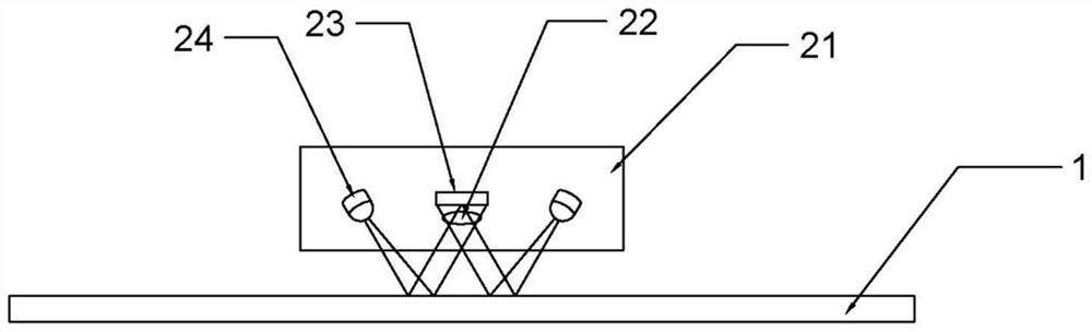
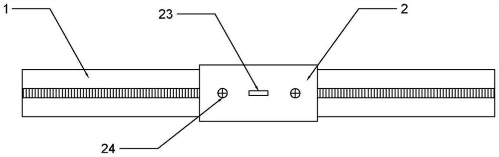
[0031] like Figure 1 to Figure 5 As shown, a grating displacement measuring device provided by the present invention includes a grating ruler 1 and a reading head 2, and relative movement can occur between the grating ruler 1 and the reading head 2; it is characterized in that: the reading head 2 It includes a casing 21 , a cylindrical lens 22 is disposed in the middle of the casing 21 , a photodiode 23 is disposed on the rear side of the cylindrical lens 22 , and two or more light sources 24 are disposed around the photodiode 23 .
[0032] In this embodiment, by arranging more than two light sources 24 around the photodiode 23, the cost is lower compared to the traditional technical solution of multiple reading heads, and actually only one reading head needs to be installed, and the installation costs The time is short; and the photodiode 23 can compare the signals of the multiple light sources 24 during the measurement process, and then output the final signal, and the sign...
Embodiment 2
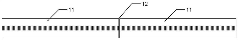
[0035] Example 2 is a further illustration of Example 1. like image 3 As shown, the grating ruler 1 is strip-shaped, and the grating ruler 1 is formed by splicing a plurality of linear gratings 11 in sequence, and the splicing gap 12 between two adjacent linear gratings 11 is smaller than that between two adjacent light sources 24 Pitch.
[0036] In the present embodiment, it is difficult to manufacture the entire linear grating 1 with a length of several meters. Therefore, a plurality of short linear gratings 11 can be manufactured first, and then the plurality of linear gratings 11 can be sequentially spliced to form a longer grating. However, there is a splicing gap 12 between two adjacent linear gratings 11; if a reading head with more than two light sources 24 is used, when one of the light sources 24 illuminates the splicing gap 12, the rest of the light sources illuminate the grating ruler 1. At valid tick marks, the readhead will still function normally.
Embodiment 3
[0038] Example 3 is a further illustration of Example 1. like Figure 5 As shown, the grating ruler 1 is disc-shaped or annular; the distances between each of the light sources 24 and the center of the grating ruler 1 are equal.
[0039] In this embodiment, the distance between each light source 24 and the center of the grating ruler 1 is set to be equal, which is equivalent to arranging each light source 24 in a concentric circle that is concentric with the grating ruler, so as to ensure that each light source 24 can At the same time, an effective focus is generated on the disc-shaped or annular grating ruler 1; thus, the measurement accuracy is ensured.
PUM
 Abstract
Description
Claims
Application Information
 - R&D
- Intellectual Property
- Life Sciences
- Materials
- Tech Scout
- Unparalleled Data Quality
- Higher Quality Content
- 60% Fewer Hallucinations
Browse by: Latest US Patents, China's latest patents, Technical Efficacy Thesaurus, Application Domain, Technology Topic, Popular Technical Reports.
© 2025 PatSnap. All rights reserved.Legal|Privacy policy|Modern Slavery Act Transparency Statement|Sitemap|About US| Contact US: help@patsnap.com