
Photoelectric rotating speed sensor

A speed sensor, photoelectric technology, applied in the field of sensors, to achieve the effect of high rotation accuracy and anti-vibration ability

Active Publication Date: 2022-07-22
NINGBO CRRC TIMES TRANSDUCER TECH CO LTD
View PDF12 Cites 0 Cited by
  • Summary
  • Abstract
  • Description
  • Claims
  • Application Information

AI Technical Summary

Problems solved by technology

Most of the existing speed sensors fix the rotating shaft of the grating with the end of the axle. When the vehicle is running, the axle rotates to drive the grating to rotate. However, when some vehicles are running, the wheel rotates but the axle does not rotate. The existing photoelectric The speed sensor is no longer suitable for wheel speed measurement in such vehicles

Method used


Image

  • Photoelectric rotating speed sensor
  • Photoelectric rotating speed sensor
  • Photoelectric rotating speed sensor

Examples


Embodiment Construction

[0026] The following are specific embodiments of the present invention and the accompanying drawings to further describe the technical solutions of the present invention, but the present invention is not limited to these embodiments.

[0027] It should be noted that all directional indications (such as up, down, left, right, front, back, etc.) in the embodiments of the present invention are only used to explain the relationship between various components under a certain posture (as shown in the accompanying drawings). The relative positional relationship, the movement situation, etc., if the specific posture changes, the directional indication also changes accordingly.

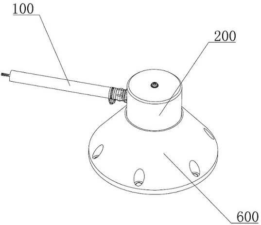
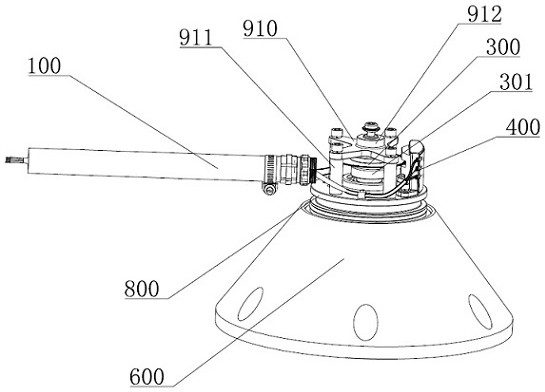
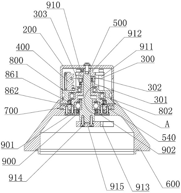
[0028] like figure 1 , figure 2 and image 3 As shown, a photoelectric speed sensor includes a connecting cable 100, a cover 200, a grating 300, and an optoelectronic module 400 matched with the grating 300. The connecting cable 100 is electrically connected to the optoelectronic module 400, and also includ...


PUM


Abstract

The invention provides a photoelectric rotating speed sensor, which comprises a connecting cable, an outer cover, a grating and a photoelectric module matched with the grating, and is characterized by further comprising a fixed shaft and a transmission disc, the transmission disc is fixed with a wheel, one end, close to the wheel, of the fixed shaft is fixed with an axle end, and the other end of the fixed shaft penetrates through the transmission disc and is rotationally connected with the transmission disc; the grating is arranged on the fixed shaft in a penetrating mode, the grating is rotationally connected with the fixed shaft, a rotating assembly is arranged between the transmission disc and the grating, so that when the transmission disc rotates, the grating can be driven to rotate, the transmission disc is covered with the outer cover, the outer cover is connected with the fixed shaft, and the photoelectric module is arranged in the outer cover. And a rotating assembly is arranged between the driving disc and the grating, so that when the wheel rotates, the driving disc drives the grating to rotate, a frequency signal proportional to the rotating speed of the wheel is generated and provided for a control system, and the device is suitable for rail transit vehicles with fixed axles and rotating wheels in the running process.

Description

technical field [0001] The invention belongs to the technical field of sensors, and in particular relates to a photoelectric rotational speed sensor. Background technique [0002] Most of the existing speed sensors use photoelectric speed sensors, which are installed at the end of the axle of the rail transit vehicle. Through the mechanical connection with the axle, the grating inside the sensor is driven to rotate with the axle, and a frequency signal proportional to the speed is generated to provide it to the control system. Providing running speed and direction signals for the vehicle is an important part of the safe operation of the vehicle. Most of the existing speed sensors fix the rotating shaft of the grating with the end of the axle, and the rotation of the axle drives the grating to rotate during the driving process of the vehicle. However, in some vehicles, the wheel rotates but the axle does not rotate. The rotational speed sensor is no longer suitable for wheel...

Claims


Application Information

Patent Timeline
Patent Type & Authority Applications(China)
IPC IPC(8): G01P3/36G01P1/00
CPCG01P3/36G01P1/00
Inventor 张燕亮吕阳赵宇恒郑华雄杨敏刘丹金波
Owner NINGBO CRRC TIMES TRANSDUCER TECH CO LTD
Learn More