Liquid cooling plate

A liquid cold plate and liquid separation technology, which is applied to electrical components, electrochemical generators, secondary batteries, etc., can solve the problems of uneven cooling temperature control, large temperature difference between inlet and outlet liquid, and large temperature difference of heat source, etc., to reduce the total The effect of long path, low head selection, and system cost reduction

Pending Publication Date: 2022-07-22
厦门科华数能科技有限公司
View PDF0 Cites 1 Cited by
  • Summary
  • Abstract
  • Description
  • Claims
  • Application Information

AI Technical Summary

Problems solved by technology

The existing liquid cooling plate does not control the cooling temperature of the battery pack uniformly. The flow channel of the liquid cooling plate generally adopts a snake-shaped one-in and one-out mode. This flow channel has no bifurcation from the beginning to the end, and the liquid in the liquid cooling plate During the flow process, the inlet temperature is low and the outlet temperature is high, that is, the temperature difference between the inlet and outlet liquids is large, which makes the temperature difference of the heat source (battery core) also large, and this design is limited in the outer size (area) of the liquid cold plate When it is larger, the flow resistance is also larger, and the bifurcated structure design tends to make the flow velocity in each branch channel inconsistent after the bifurcation, some areas have fast flow velocity, some areas have slow flow velocity, and the overall temperature uniformity is poor

Method used


Image

  • Liquid cooling plate
  • Liquid cooling plate
  • Liquid cooling plate

Examples


Embodiment 1

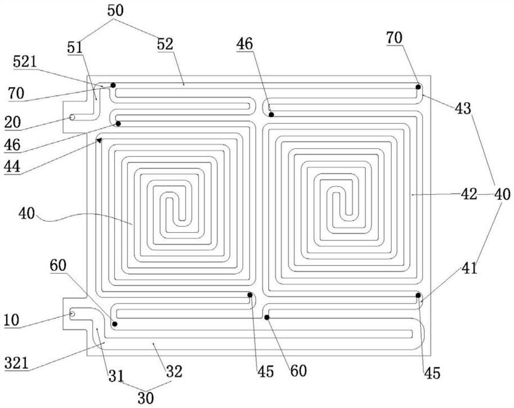
[0045] see figure 1 and Image 6 , figure 1 A liquid cooling plate is shown for cooling battery modules, ref. Image 6 , the battery module includes at least two battery packs 80 arranged along the first direction. In this embodiment, the battery module is formed into a rectangle, the length direction of the battery pack rectangle is the first direction, and the width direction is perpendicular to the first direction. the second direction, Image 6 , each cell group 80 may include 4 cells arranged along the second direction, figure 1 and Image 6 Among them, the first direction is the left-right direction, and the second direction is the up-down direction.

[0046] The liquid-cooling plate is a rectangular structure corresponding to the battery module. The liquid-cooling plate is parallel to the first direction. The left end of the liquid-cooling plate protrudes with two protrusions extending in the first direction, and the two protrusions extend in the second direction. ...

Embodiment 2

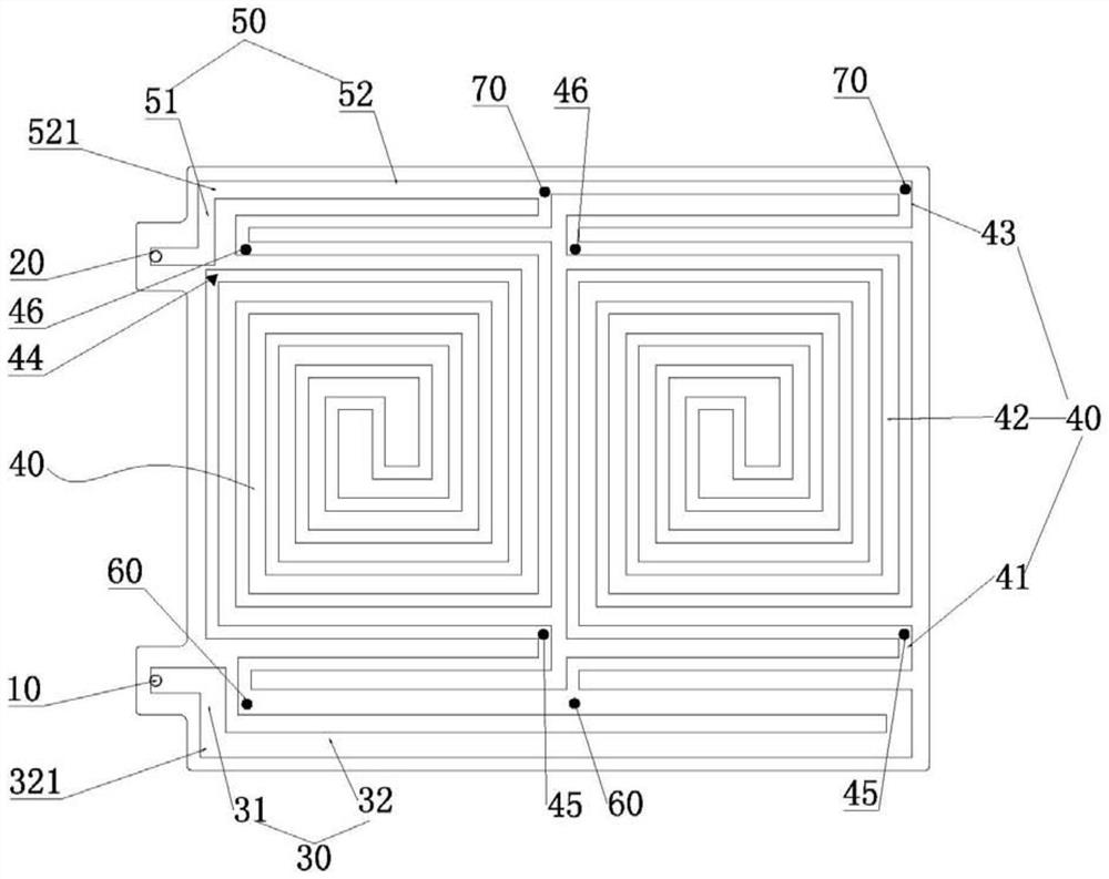
[0059] see figure 2 , the structure of Example 2 is basically the same as that of Example 1, and the number of liquid separation channels 40 is also two. The difference is that the liquid separation outlet 70 is on the same side as the second position 45, and the liquid separation inlet 60 is on the same side as the third position. 46 on the same side, the first segment 41 and the third segment 43 are both Z-shaped structures. In this way, the structure of each liquid separation flow channel 40 is relatively consistent, the structure is more concise, the production process is simple, and it is avoided that the third section 43 is too long and the heat flow is concentrated on the side close to the liquid outlet flow channel 50, and the liquid outlet port 20 is avoided. Temperature is too high.

[0060] The ratio of the length from the first position 44 to the corresponding liquid separation inlet 60 to the length from the first position 44 to the corresponding liquid separati...

Embodiment 3

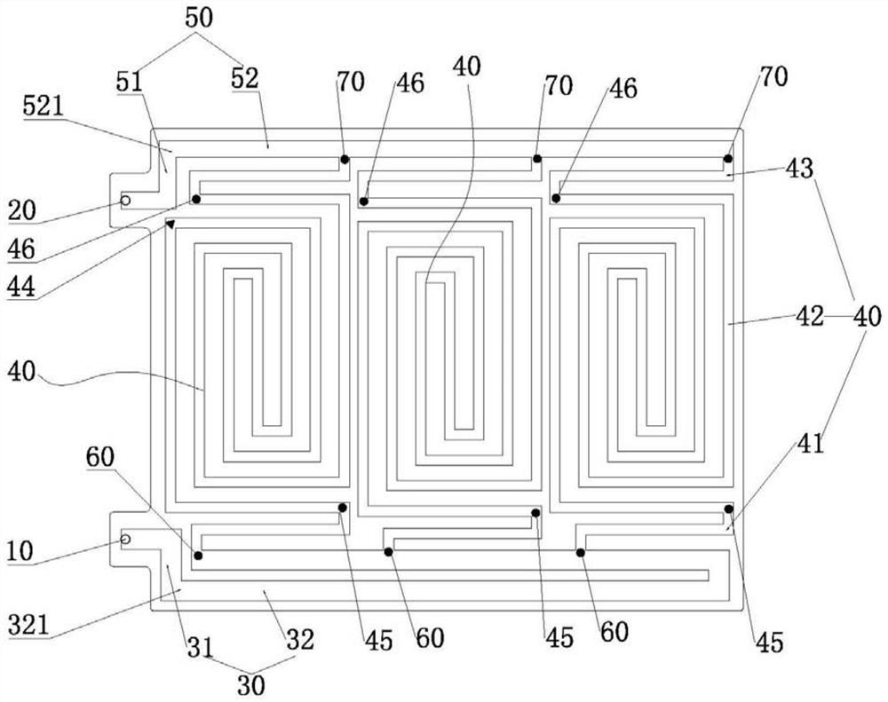
[0063] see image 3 , the structure of Example 3 is basically the same as that of Example 2, the difference is that the number of liquid separation channels 40 is three, and the length from the first position 44 to the corresponding liquid separation inlet 60 is the same as the first position 44 to the corresponding liquid separation inlet 60. The ratio of the length of the liquid separation outlet 70 is 1:1.8.

[0064] In addition, under the condition that the area of ​​the liquid cooling plate remains unchanged, in the arrangement of the three liquid-separating flow channels 40, the zigzag coiled structure is more sparse than the zigzag coiled structure of the second embodiment.


PUM


Abstract

The invention discloses a liquid cooling plate which is used for cooling a battery module, the liquid cooling plate is parallel to a first direction, one side of the liquid cooling plate along the first direction is provided with a liquid inlet port and a liquid outlet port along a second direction, and a flow channel is formed between the liquid inlet port and the liquid outlet port. The flow channel comprises a liquid inlet flow channel connected with the liquid inlet port, a liquid outlet flow channel connected with the liquid outlet port and at least two liquid separation flow channels arranged corresponding to the battery cell group, at least part of each liquid separation flow channel is coiled in a rectangular-ambulatory-plane shape, the liquid separation flow channels and the liquid inlet flow channel are intersected at a liquid separation inlet, and the liquid separation flow channels and the liquid outlet flow channel are intersected at a liquid separation outlet; each liquid separation inlet is arranged along a first direction, and each liquid separation outlet is arranged along the first direction; the lengths of the liquid separation runners are equal, and the sum of the lengths from the liquid separation inlets to the liquid inlet ports is equal to or similar to the sum of the lengths from the corresponding liquid separation outlets to the liquid outlet ports. According to the liquid cooling plate provided by the invention, the flow velocity of the liquid in each liquid separation flow channel is equal or similar, the flow velocity of the liquid in each region is relatively balanced, and the temperature of the liquid cooling plate is more balanced.

Description

technical field [0001] The invention relates to the technical field of battery thermal management, in particular to a liquid cooling plate. Background technique [0002] The temperature factor is an important factor affecting the performance and life of the battery. In the process of charging and discharging, the battery module will inevitably generate heat. Therefore, in the battery field, a liquid cooling plate is usually installed in the battery module to improve the heat dissipation efficiency of the battery. , each cell group consists of multiple cells. The existing liquid-cooling plate does not uniformly control the cooling temperature of the cell group. The liquid-cooling plate flow channel generally adopts a snake-shaped one-in and one-out mode. This kind of flow channel has no bifurcation from the beginning to the end, and the liquid in the liquid-cooling plate During the flow, the inlet temperature is low and the outlet temperature is large, that is, the temperat...

Claims


Application Information

Patent Timeline
Patent Type & Authority Applications(China)
IPC IPC(8): H01M10/6568H01M10/613H01M10/617H01M10/6554H01M10/6556
CPCH01M10/6568H01M10/613H01M10/617H01M10/6554H01M10/6556
Inventor 倪泽联梁峰卢艺杰赵晓航
Owner 厦门科华数能科技有限公司
Why Eureka
Try Eureka