
Feed type closed bus duct

A closed busway technology, which is applied in the direction of fully enclosed busbar devices, can solve the problems of equipment damage, waste of equipment use, and reduced service life of the device

Inactive Publication Date: 2022-07-22
陆柳蕙
View PDF0 Cites 1 Cited by
  • Summary
  • Abstract
  • Description
  • Claims
  • Application Information

AI Technical Summary

Problems solved by technology

[0003] However, the existing busbars are all in a fixed mode, and the number of busbars is fixed. The same number of busbars are used in the power transmission of different powers. When the transmission power is too large, the number of busbars will be relatively small. , the load of a single busbar is large, which is easy to cause damage to the equipment, and the transmission power is too small, the number of busbars will be relatively large, and the load of a single busbar is too small, resulting in waste of equipment use; in actual use According to the usage specification, the busway needs to be hoisted at a position one meter below the ceiling, and multiple busway connections are often required in power transmission. The positional relationship needs to be calculated in advance before hoisting. However, in actual use, uneven walls, The error generated during hoisting may cause the busway not to be in the horizontal position. When the two busways to be connected have a busway that is inclined, the butted interface cannot be kept horizontal, and the forced connection will cause distortion, resulting in shearing The force will reduce the service life of the device, so it needs to be recalculated and re-lifted, which wastes a lot of manpower and material resources

Method used


Image

  • Feed type closed bus duct
  • Feed type closed bus duct
  • Feed type closed bus duct

Examples


Embodiment Construction

[0030] In order to make the objectives, technical solutions and advantages of the present invention clearer, the present invention will be further described in detail below with reference to the accompanying drawings and embodiments. It should be understood that the specific embodiments described herein are only used to explain the present invention, but not to limit the present invention.

[0031] It should be noted that when an element is referred to as being "fixed to" or "disposed on" another element, it can be directly on the other element or indirectly on the other element. When an element is referred to as being "connected to" another element, it can be directly connected to the other element or indirectly connected to the other element.

[0032] In the description of the present invention, it should be understood that the terms "length", "width", "upper", "lower", "front", "rear", "left", "right", "vertical", The orientations or positional relationships indicated by "...


PUM


Abstract

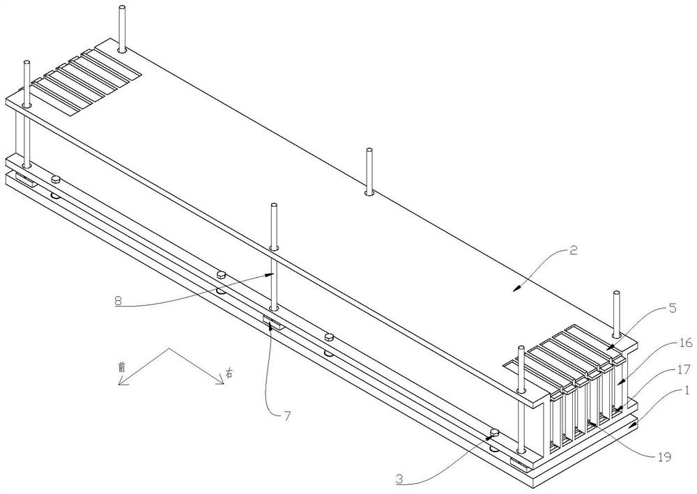
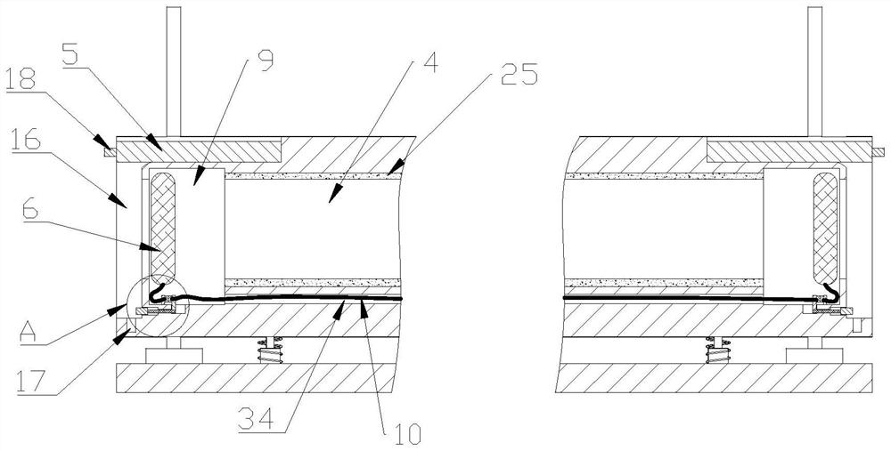
A feed type closed bus duct comprises a bearing plate, a protection shell and fine adjustment devices, the protection shell is located over the bearing plate and is in an I shape, the protection shell and the bearing plate are connected through a plurality of fine adjustment devices which are evenly distributed, and a plurality of wire row holes which are evenly distributed at equal intervals are formed in the protection shell. Sealing covers are arranged at the positions, corresponding to the wire row holes, of the left end and the right end of the protection shell, the left end and the right end of each wire row hole are each provided with a detection space in a communicating mode, and a feed device is arranged in each detection space. The bus bar is inserted into the protection shell through the wire bar hole, the feed device corresponding to the bus bar is attached to the bus bar, the feed devices at the two ends of the wire bar hole are electrically communicated to form a complete detection circuit, and when a plurality of bus ducts are assembled and used, the distance between the protection shell and the bearing plate is adjusted through the fine adjustment device. When the bearing plate inclines due to the hoisting problem, the inclination angle of the protective shell is properly adjusted, so that the protective shell is kept in a horizontal state.

Description

technical field [0001] The invention relates to the field of electrical equipment, and particularly provides a feed-type closed bus duct. Background technique [0002] The busway is a closed metal device composed of copper and aluminum busbars, which is used to distribute large power to each component of the dispersion system. It has increasingly replaced wires and cables in indoor low-voltage power transmission trunk projects. With the emergence of modern engineering facilities and equipment, the power consumption of all walks of life has increased rapidly, especially many high-rise buildings and large workshops. With the emergence of workshops, traditional cables as transmission conductors can no longer meet the requirements in high-current transmission systems, and the parallel use of multi-channel cables brings a lot of inconvenience to on-site installation and construction connections. The plug-in bus duct emerges as a new type of distribution wire. Compared with the t...

Claims


Application Information

Patent Timeline
Patent Type & Authority Applications(China)
IPC IPC(8): H02G5/06
CPCH02G5/06
Inventor 陆柳蕙
Owner 陆柳蕙
Learn More