
Foldable rotating arm structure and device of bicycle

A technology for bicycles and pivoting arms, applied in the field of foldable pivoting arm structures and devices of bicycles, which can solve the problems of inconvenient application, limited space, and large volume, so as to avoid looping lines, increase angular momentum or balance moment, and reduce height effect of space

Pending Publication Date: 2022-07-26
刘鹏军
View PDF2 Cites 0 Cited by
  • Summary
  • Abstract
  • Description
  • Claims
  • Application Information

AI Technical Summary

Problems solved by technology

[0002] Unmanned bicycles, self-driving bicycles, and two-wheeled vehicles need gyro balance devices to maintain them in a static state, but the space for placing gyro devices on light bicycle frames is very limited. Patent No. CN201753096U mentions a flywheel placed on a horizontal tube, which is large in size , it is not convenient for normal riding, and it is difficult to be practical
Currently CN111874141A discloses a balance device for an electric bicycle and an electric bicycle. The battery frame surrounding the driving motor has a built-in battery, and the weight of the battery is used as a momentum wheel, which reduces the extra flywheel counterweight and has a large capacity, but its frame structure cannot be folded; The axis of the battery is parallel to the drive motor, and the radial or axial space occupied by the battery cannot be effectively reduced when the battery is folded in a radially multi-layer stacked arrangement
The arrangement shown results in a large increase in mass, but a small increase in radius. The increase in angular momentum mainly depends on the increase in mass, and the required starting torque is constant. It is not portable

Method used


Image

  • Foldable rotating arm structure and device of bicycle
  • Foldable rotating arm structure and device of bicycle
  • Foldable rotating arm structure and device of bicycle

Examples


Embodiment 1

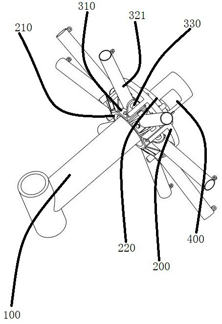
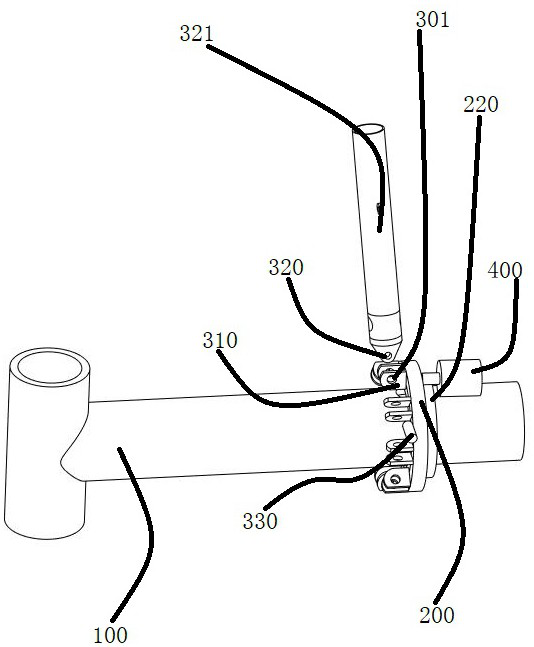
[0037] In Embodiment 1, the runner 200 and the transmission element 220 may be integrated, or may be combined and connected in separate parts.

[0038] Embodiment 1, the bracket base 310 and the boss of the runner 200 are as follows figure 1 or the side of the runner such as figure 2 .

Embodiment 2

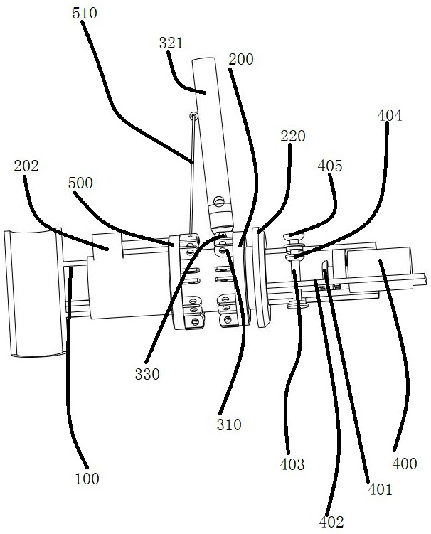
[0040] In Embodiment 2, the turntable 220 and the runner 200 may be integrated, or may be a fixed connection combination of separate parts, and are rotatably connected to the horizontal tube 100 through a bearing.

[0041] In Embodiment 2, the lead screw motor 202 is between two adjacent rotating arms 321 , and the lead screw on the output shaft of the lead screw motor 202 is connected to the nut hole on the storage wheel 500 .

specific Embodiment 3

[0042] like Figure 4Specific embodiment 3, a foldable rotating arm structure and device of a bicycle, including a transverse tube 100, a runner 200, a bracket base 310, a rotating arm 321, and a rotating arm connecting seat 320, and the main body of the runner 200 is between the two horizontal tubes. , the stator part of the driving device 400 is fixedly connected with the central shaft 103, the central shaft 103 is fixedly connected with the flange 102, and is fastened by fasteners 101, such as bolts, the flange 102 is fixedly connected with the horizontal tube 100, and the outer diameter of the flange 102 It is equal to or smaller than the outer diameter of the transverse tube 100 and is connected by fasteners. The same is true for the connection between the central axis 103 and the transverse tube 110 . The rotor part of the driving device 400 has mounting holes and is connected to the runner 200 through fasteners, so as to drive the runner 200 and the rotating arm 321 to ...


PUM


Abstract

The foldable rotating arm structure comprises a rotating wheel and a rotating arm, and is characterized in that the rotating wheel is coaxial with a transverse pipe or surrounds the transverse pipe; the rotating arm is in steering connection with the rotating wheel or the support base so that the rotating arm can be attached to the transverse pipe when folded, and occupied upward space of the transverse pipe is reduced. The invention discloses a flywheel for balancing devices and interesting devices of bicycles and boosting bicycles. Through the arrangement mode that single batteries or multi-stage batteries are arranged in a radial single-layer mode and axially stacked in a multi-stage mode in the rotating arm, the angular momentum or the balance moment is increased during unfolding rotation, the rotating arm is parallel to the transverse pipe during folding, the mass center radius is small, and the moment is small, so that the rotating motor can be quickly started conveniently.

Description

technical field [0001] A foldable rotating arm structure and device of a bicycle are used in the fields of bicycles and power-assisted bicycles. Background technique [0002] Unmanned bicycles, self-driving bicycles, and two-wheeled vehicles need a gyro balance device to maintain in a stationary state, but the space for placing the gyro device on the light bicycle frame is very limited. , it is inconvenient for normal riding and difficult to be practical. At present, CN111874141A discloses an electric bicycle balancing device and an electric bicycle. The battery frame surrounding the driving motor has a built-in battery, and the weight of the battery is used as the momentum wheel, which reduces the extra flywheel weight and has a large capacity, but the frame structure cannot be folded; The axis of the battery is parallel to the drive motor, and the radial or multi-layered arrangement of the batteries cannot effectively reduce the radial or axial space occupied when folded....

Claims


Application Information

Patent Timeline
Patent Type & Authority Applications(China)
IPC IPC(8): B62J50/00B62K15/00
CPCB62J50/00B62K15/00
Inventor 刘鹏军
Owner 刘鹏军
Learn More