Control method for keeping constant temperature of glue solution

A control method and constant temperature controller technology, applied to the surface coating liquid device, coating, etc., can solve the problems of large heat dissipation noise, low heat dissipation flow rate, waste of compressed air, etc., to achieve the improvement of glue output stability, Avoid voltage shock and improve service life

Active Publication Date: 2022-07-29
CHANGZHOU MINGSEAL ROBOT TECH CO LTD
View PDF8 Cites 0 Cited by
  • Summary
  • Abstract
  • Description
  • Claims
  • Application Information

AI Technical Summary

Problems solved by technology

[0005] The heat dissipation of Peltier semiconductors usually uses a rear heat sink and a fan for heat dissipation. This heat dissipation method is not suitable for dust-free workshops. Fan heat dissipation will affect the dust-free conditions of the product work area.
When compressed air is used for heat dissipation, the heat dissipation flow rate is low, which will lead to insufficient heat dissipation and affect the cooling effect. Excessive heat dissipation pressure will result in loud heat dissipation noise and waste of compressed air

Method used


Image

  • Control method for keeping constant temperature of glue solution
  • Control method for keeping constant temperature of glue solution
  • Control method for keeping constant temperature of glue solution

Examples


Embodiment 1

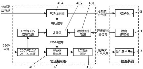
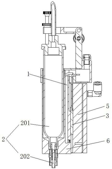
[0034] See figure 1 , figure 2 and image 3 , a control method of the present invention for maintaining a constant temperature of glue liquid, the valve seat in the constant temperature device is controlled by the constant temperature controller 4 to maintain a constant temperature, and the constant temperature device includes a temperature sensor 1, a glue dispenser 2, a Peltier semiconductor 3, a heat sink 5 And the valve seat 6 , the temperature sensor 1 , the glue dispenser 2 and the Peltier semiconductor 3 are all mounted on the valve seat 6 , wherein the glue dispenser 2 includes a first glue barrel 201 and a first nozzle 202 . The thermostatic controller 4 includes a temperature detection circuit 401 , a processor 402 , an LC low-pass filter 403 , a pneumatic proportional valve 404 and an H-bridge drive circuit 405 .

[0035] Specifically, an accommodating cavity is defined in the barrel of the valve seat 6 , and the glue dispenser 2 can be installed in the accommoda...

Embodiment 2

[0092] See figure 1 , figure 2 and Figure 4 , for ease of understanding Figure 4 Structure, Figure 4 The middle valve seat 6 and the glue dispenser 2 are in a separated state. Compared with the first embodiment, the difference between the second embodiment and the second embodiment is that the glue dispenser 2 includes the second glue. The barrel 203 , the second nozzle 204 , the flow channel 205 and the piezoelectric valve body 206 , the second rubber barrel 203 and the piezoelectric valve valve body 206 are installed above the flow channel 205 , and the second nozzle 204 is located on the piezoelectric valve valve body 206 Just below the temperature sensor 1 is embedded in the embedded groove of the valve seat 6 . During assembly, the flow channel 205 needs to be assembled into the valve seat 6 , and the second nozzle 204 is matched with the assembly hole on the valve seat 6 .


PUM


Abstract

The invention discloses a control method for keeping constant temperature of a glue solution. The control method comprises the following steps: receiving a temperature signal of a temperature sensor in a valve seat through a constant temperature controller; the real-time temperature deviation value between the current temperature of the valve seat and the set target temperature is judged; calculating the power required by the Peltier semiconductor according to the real-time temperature deviation value, and judging whether to adopt a heating control mode or a refrigeration control mode according to the change trend of the real-time temperature deviation value; and the output voltage and the output current direction of the Peltier semiconductor are controlled, and the constant temperature device is kept at a constant set target temperature. According to the control method, the constant temperature controller can adjust the output power of the Peltier semiconductor and switch the heating mode and the cooling mode by controlling the voltage and the current direction of the Peltier semiconductor, constant temperature control over the constant temperature device is achieved, and the glue outlet stability of the glue dispensing system is obviously improved.

Description

technical field [0001] The invention relates to the technical field of constant temperature control methods, in particular to a control method for maintaining a constant temperature of glue liquid. Background technique [0002] In the field of precision dispensing, the fluidity and viscosity of common glues are greatly affected by temperature, and unstable glue temperature will reduce the stability of dispensing. [0003] The working principle of the dispensing device is to quickly inflate and exhaust the inside of the dispenser, which will cause the piston in the dispenser to move rapidly and generate heat continuously. In addition, the working environment of the dispenser is usually in a closed space. In addition, the heating of other equipment will also cause the temperature of the dispenser to change, which will cause the temperature of the glue to continue to rise, which will adversely affect the stability of the dispensing. The above conditions require refrigeration co...

Claims


Application Information

Patent Timeline
Patent Type & Authority Applications(China)
IPC IPC(8): B05C5/00B05C5/02
CPCB05C5/001B05C5/02
Inventor 冒洋洋曲东升李长峰耿玉新上官鑫龙闵继江戴敬桐
Owner CHANGZHOU MINGSEAL ROBOT TECH CO LTD
Why Eureka
Try Eureka