Pneumatic front chuck

A front-mounted, pneumatic technology, applied in the direction of measuring devices, electrical components, instruments, etc., can solve problems such as affecting cutting, slow response, and insufficient clamping, so as to improve the smoothness of movement, reduce manufacturing costs, and ensure clamping. The effect of precision

Pending Publication Date: 2022-07-29
常州戴芮珂机电科技有限公司
View PDF0 Cites 0 Cited by
  • Summary
  • Abstract
  • Description
  • Claims
  • Application Information

AI Technical Summary

Problems solved by technology

Occasionally, when the traditional pneumatic chuck is doing the clamping action, the clamping force is too large or the clamping is not in place. When the clamping force is too large, the surface of the workpiece will be damaged, and the clamping will not be in place. Affect normal cutting. These faults often rely on field operators to judge by experience. When they are discovered, they have already caused a certain scale of impact on the normal cutting production of the workpiece, and the response is slow.

Method used


Image

  • Pneumatic front chuck
  • Pneumatic front chuck
  • Pneumatic front chuck

Examples


Embodiment Construction

[0027] In order to better understand the above technical solutions, the above technical solutions will be described in detail below with reference to the accompanying drawings and specific embodiments.

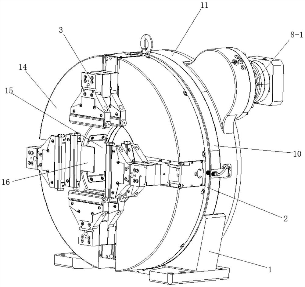
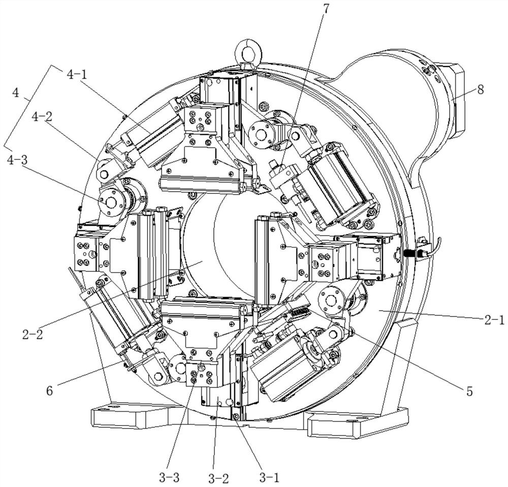
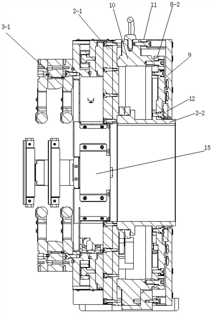
[0028] like Figure 1 to Figure 4 The shown intelligent pneumatic chuck includes a base 1 and a rotating body 2 that is rotatably mounted on the base 1 and rotates around itself. The front end of the rotating body 2 is provided with a clamping assembly 3, and a pneumatic clamping driving device 4 is provided inside. , the circuit board 5, and the displacement detection device 6 and the air pressure detection device 7 connected with the pneumatic clamping drive device 4, wherein the displacement detection device 6 and the air pressure detection device 7 are both electrically connected with the circuit board 5, and the circuit board is connected to the external system, which can The pneumatic clamping drive device 4 of the chuck is monitored in real time to ensure the clamping a...


PUM


Abstract

The invention discloses a pneumatic front chuck which comprises a base and a rotating body which is rotationally installed on the base and rotates around the rotating body, and a clamping assembly is arranged at the front end of the rotating body. A pneumatic clamping driving device, a circuit board, and a displacement detection device and an air pressure detection device which are connected with the pneumatic clamping driving device are arranged in the rotating body, and the displacement detection device and the air pressure detection device are both electrically connected with the circuit board; the pneumatic clamping driving device is suitable for driving the clamping assembly to act, and the displacement detection device and the air pressure detection device are suitable for detecting the displacement and the air pressure of the pneumatic clamping driving device respectively. Through the displacement detection device and the air pressure detection device, the pneumatic clamping driving device of the chuck can be monitored in real time, the clamping precision of the chuck is ensured, and when a fault occurs, an alarm can be given to an external system through the circuit board in time, so that a maintainer is reminded to deal with the fault, and the fault influence is reduced to the minimum.

Description

technical field [0001] The invention relates to the technical field of chucks, in particular to a pneumatic front chuck. Background technique [0002] During the cutting process of the laser cutting machine, the beam is focused into a small focal point by the lens of the cutting head, so that a high power density can be achieved at the focal point. At this time, the heat input by the beam far exceeds the part of the heat reflected, conducted or diffused by the material, and the material is quickly heated to the melting and vaporizing temperature. With the relative movement of the focus and the material, the hole forms a continuous narrow width. Cut seams to complete the cutting of the material. [0003] In order to ensure that the workpiece can be rotated smoothly during laser cutting to achieve uniform cutting, the workpiece is often fixed on a pneumatic chuck. The pneumatic chuck is provided with a rotating body, the front side of the rotating body is provided with a cla...

Claims


Application Information

Patent Timeline
Patent Type & Authority Applications(China)
IPC IPC(8): B23K26/70B23K26/12B23K26/38H01R39/08H01R39/26G01L11/00G01B21/02
CPCB23K26/702B23K26/12B23K26/38H01R39/08H01R39/26G01L11/00G01B21/02
Inventor 曹卉陈超葛鹏
Owner 常州戴芮珂机电科技有限公司
Why Eureka
Try Eureka