Machining method for micro-miniature part with open hole

A processing method and micro-miniature technology, applied in metal processing, metal processing equipment, manufacturing tools, etc., can solve the problems of excessive size and position deviation, and difficult to remove burrs, so as to reduce the opening error and simplify the deburring steps. , the effect of easy operation

Pending Publication Date: 2022-07-29
国泰达鸣精密科技集团有限公司
View PDF0 Cites 1 Cited by
  • Summary
  • Abstract
  • Description
  • Claims
  • Application Information

AI Technical Summary

Problems solved by technology

[0003] The purpose of the present invention is to provide a processing method for micro-sized parts with openings, aiming at solving the problem that in the prior art, using a lathe to drill holes for micro-sized parts will lead to excessive size and position deviation and the resulting burrs are not easy to remove technical issues

Method used


Image

  • Machining method for micro-miniature part with open hole
  • Machining method for micro-miniature part with open hole
  • Machining method for micro-miniature part with open hole

Examples


Embodiment 1

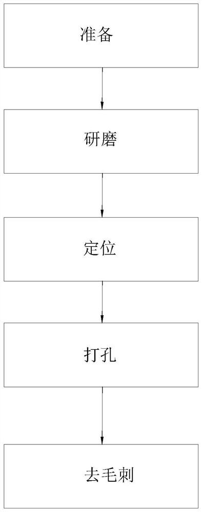
[0038] see Figure 4 , The method for processing micro-miniature parts with openings 21 provided in the first embodiment includes the following steps: preparation, grinding, positioning, drilling, deburring, regrinding, demagnetization and preparation for shipment.

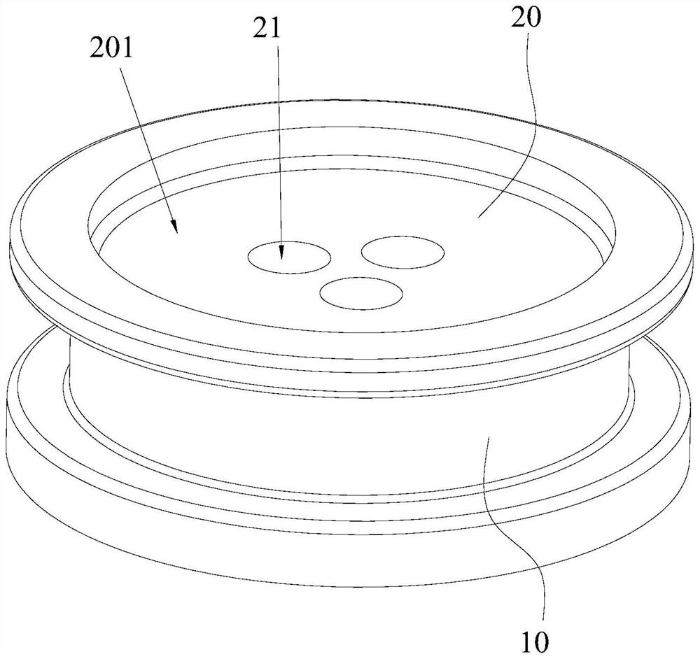
[0039] In the preparation step, the stainless steel material is first prepared, and the features of the product to be punched are turned by the CNC lathe. The product to be punched is made of stainless steel as a whole. part. Specifically, the cross-sectional outer diameter of the product to be punched in this embodiment is 3.35 mm, and the thickness is 1.225 mm. see figure 2 and image 3 , the product to be punched includes a cylinder 10 and a panel 20 sealed at one end of the cylinder 10, the other end of the cylinder 10 is open, the section of the cylinder 10 is circular, and the panel 20 is a circular shape that fits with the cylinder 10. The thickness of the panel 20 from the surface to be punched to the...

Embodiment 2

[0061] The second embodiment provides a method for processing micro-miniature components with openings 21. The difference between the second embodiment and the first embodiment is the deburring step. In the second embodiment, the deburring step includes: first The burrs are removed by blasting dry ice and then by sandblasting.

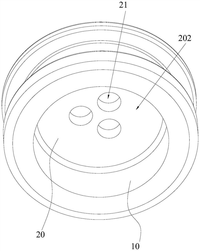
[0062] In the step of spraying dry ice for deburring, it is also carried out twice. The first time is to spray dry ice in the direction from the back side 202 to the grinding surface 201 to blow off part of the burrs and slag, and a small part of the burrs or slag may pass through The opening 21 is blown toward the grinding surface 201 , and the second time is to spray dry ice from the grinding surface 201 to the back surface 202 to blow off the scattered burrs or slag on the grinding surface 201 .

[0063]Since the dry ice on the panel 20 absorbs heat, water vapor will be generated on the panel 20. Therefore, the perforated product after spraying dry ...


PUM

PropertyMeasurementUnit
thicknessaaaaaaaaaa
diameteraaaaaaaaaa
thicknessaaaaaaaaaa

Abstract

The invention provides a processing method of a micro-miniature part with an open pore, which comprises the following steps: preparing, grinding, positioning, punching and deburring: in the preparation step, preparing a product to be punched; in the grinding step, a to-be-punched surface of the to-be-punched product is ground to form a grinding surface, and the light reflectivity of the grinding surface is smaller than that of the to-be-punched surface; in the positioning step, an optical image capturing device is adopted to position a position to be punched on a grinding surface; in the punching step, laser punching is conducted on the position to be punched, and a punched product is formed. In the deburring step, burrs on the periphery of the open hole are removed, and a deburring product is formed. According to the method, the grinding face with the light reflectivity smaller than that of the face to be punched is ground, so that the influence of reflected light on positioning is reduced, the punching error can be reduced through laser punching, meanwhile, burrs cannot appear on the hole wall of the punched hole, the burrs only appear on the back face, the deburring step is simplified, and operation is convenient.

Description

technical field [0001] The invention belongs to the technical field of sensor perforation processing, and in particular relates to a processing method for micro-miniature parts with openings. Background technique [0002] Sensor technology, communication technology and computer technology are the three pillars of modern information technology. Sensor is the product of science and engineering, which depends not only on new phenomena and new laws of science, but also on new technologies and new processes. With the development of science and technology and the progress of the times, sensors are updated quickly, the demand is large, and the demand is growing rapidly. Therefore, the components of micro and small electronic devices, such as stainless steel components on sensors, have great market prospects. At present, the part of the sensor produced and processed by the company has a cylindrical structure with one end sealed. The end plate of the sealed end of the part needs to o...

Claims


Application Information

Patent Timeline
Patent Type & Authority Applications(China)
IPC IPC(8): B23P23/04B23K26/382B23K26/70B23K26/03B24B1/00B24B9/04B23K101/36
CPCB23P23/04B23K26/032B23K26/0093B23K26/382B23K26/702B24B1/00B24B9/04B23K2101/36
Inventor 杨贞蒋承志易兰兰曾柳丹魏晶
Owner 国泰达鸣精密科技集团有限公司
Why Eureka
Try Eureka