
Automatic packaging equipment for optical filter switcher

A technology of packaging equipment and switching devices, which is applied in the direction of packaging automatic control, packaging, packaging machines, etc., can solve the problems of inability to warn the staff and low work efficiency, and achieve the effects of reducing operation troubles, improving work efficiency, and facilitating packaging

Pending Publication Date: 2022-07-29
赣州市奥海纳光电有限公司
View PDF0 Cites 0 Cited by
  • Summary
  • Abstract
  • Description
  • Claims
  • Application Information

AI Technical Summary

Problems solved by technology

[0005] Aiming at the deficiencies of the prior art, the present invention provides an automatic packaging device for a filter switcher that can warn the staff and improve the packaging effect, so as to overcome the inability of the existing packaging equipment to warn the staff, resulting in low work efficiency. low disadvantage

Method used


Image

  • Automatic packaging equipment for optical filter switcher
  • Automatic packaging equipment for optical filter switcher
  • Automatic packaging equipment for optical filter switcher

Examples


Embodiment 1

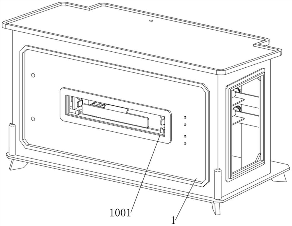
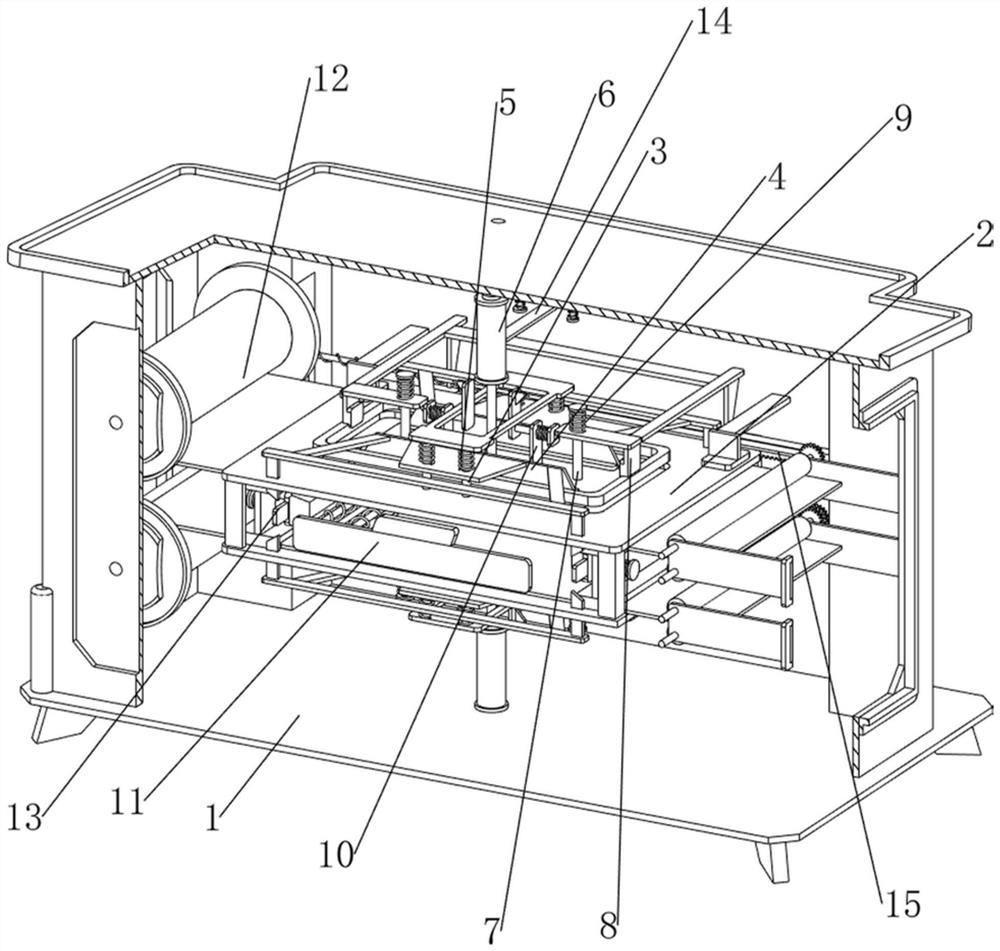
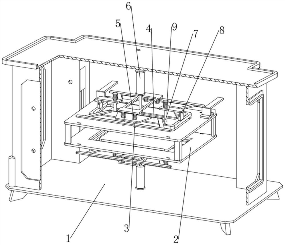
[0083] A filter switcher automatic packaging equipment, see figure 1 , figure 2 , image 3 and Figure 4 , including the outer connection frame 1, the feed port 1001, the opening 11001, the square port 11002, the inner connection frame 2, the through hole 11003, the connection frame 3, the sliding pressure plate 4, the first spring 5, the cylinder 6, the button 61, the support rod 7. The heater 8, the second spring 9, the release mechanism 10 and the positioning driving mechanism 11. The outer connecting frame 1 has a feeding port 1001 in the middle of the front side, and an opening 11001 is opened on the left rear side of the top of the outer connecting frame 1. The outer connecting frame 1. There is a square opening 11002 in the middle of the rear side, an inner connecting frame 2 is welded in the middle of the outer connecting frame 1, a through hole 11003 is opened on the rear side of the left part of the inner connecting frame 2, and a connecting frame 3 is welded on t...

Embodiment 2

[0088] On the basis of Example 1, see figure 2 and Figure 11 It also includes a film-adding mechanism 12, which is convenient for placing the film cloth. The film-adding mechanism 12 includes a winding wheel 1201, a packaging film 1202, a fixing plate 1203 and a rotating drum 1204. The left side of the outer connecting frame 1 is rotated and installed. There are two detachable winding wheels 1201, both of which are covered with a packaging film 1202, four fixing plates 1203 are welded on the right side of the outer connecting frame 1, and the left part of the two fixing plates 1203 on the upper side is There are two rotating rollers 1204 connected in rotation between the left part of the two fixed plates 1203 on the lower side and the lower side. The rotating rollers 1204 are used to drive the packaging film 1202 to move, and one end of the upper packaging film 1202 passes through the inner connecting frame. 2 is located between the two rotating drums 1204 on the upper side...


PUM


Abstract

The invention relates to automatic packaging equipment, in particular to automatic packaging equipment for an optical filter switcher. The invention provides the automatic packaging equipment for the optical filter switcher, which can warn workers and improve the packaging effect. An optical filter switcher automatic packaging device comprises an outer connecting frame, an opening is formed in the left rear side of the top of the outer connecting frame, and a square opening is formed in the middle of the rear side of the outer connecting frame; the inner connecting frame is connected to the middle of the interior of the outer connecting frame, and a through hole is formed in the rear side of the left portion of the inner connecting frame; the top and the bottom of the inner connecting frame are both connected with the connecting frames. The optical filter switcher drives the sliding plate to move backwards so as to drive the pushing rod to move backwards, so that the pushing rod extrudes the second clamping plate to move upwards, and therefore, a worker can be warned, the optical filter switcher can be ensured to be located between the two sliding pressing plates, and the packaging effect of the optical filter switcher is improved.

Description

technical field [0001] The invention relates to an automatic packaging device, in particular to an automatic packaging device for a filter switcher. Background technique [0002] After the filter switcher is produced, the filter switcher needs to be packaged, so that the filter switcher can be easily stored, and the filter switcher can be protected to avoid affecting the filter switcher. Sales. [0003] The patent publication number is CN214357088U, which discloses a fully automatic packaging equipment, including fully automatic packaging equipment, a machine table is arranged on the fully automatic packaging equipment, the interior of the machine table is provided with a packaging film roll A near the top, and the center of the upper surface of the machine table is provided. There is a sealing groove, one side of the sealing groove is symmetrically provided with a support plate to push the cylinder, and the support plate on the push shaft of the support plate pushes the cy...

Claims


Application Information

Patent Timeline
IPC IPC(8): B65B9/02B65B41/12B65B51/14B65B35/56B65B65/00B65B57/18
CPCB65B9/02B65B41/12B65B51/14B65B35/56B65B65/00B65B57/18
Inventor 张学智高睿肖莘耀董表谢超郭林生
Owner 赣州市奥海纳光电有限公司
Learn More