Polar region pipeline electric heat tracing system

A pipeline electric and axis technology, applied in the field of polar pipeline electric heat tracing system, can solve the problems of affecting construction progress, complicated construction, low efficiency, etc., and achieve the effects of improving construction efficiency, reducing manual winding, and accurate positioning

Pending Publication Date: 2022-07-29
舟山惠生海洋工程有限公司
View PDF2 Cites 0 Cited by
  • Summary
  • Abstract
  • Description
  • Claims
  • Application Information

AI Technical Summary

Problems solved by technology

Since the project is located in the polar climate and is in winter all the year round, it poses great challenges to the temperature control of all pipelines, so an electric heating system is needed to ensure that the polar pipelines maintain a stable temperature to complete the transportation of liquefied natural gas;
[0003] In the Chinese patent CN204187284U, an electric heat tracing control system for oil pipelines is disclosed, including a temperature sensor, a controller and an alarm device, wherein the temperature sensor is installed on the wall of the oil pipeline of the electric heat tracing cable and connected to the controller for Detect the temperature condition in the oil pipeline, and send the detected temperature value to the controller: the controller is connected to the alarm device, which is used to control the alarm device to send an alarm when the received temperature value is greater than the preset value. This patented oil pipeline The electric heat tracing control system can ensure the reliable operation of the electric heat tracing system. In the Chinese patent CN201810776301.1, a long-distance pipeline electric heat tracing system and its laying method are disclosed. This patent adopts a single-core serial type constant power heating cable, In the case of a control panel controlling the heating cable, according to the length of the pipe to be heated and the required heat tracing, the cross-sectional area and conductivity of the heating cable that can meet the requirements are calculated through the corresponding formula. After testing, in a set of power supply and When the control panel is powered by the heating cable, the length of the heating cable can reach 30KM or even longer, that is, it can heat the pipe to be heated more than 30KM long, which greatly simplifies the structure of the electric heating system, and only needs a set of control The cabinet occupies a small space and the structure is convenient for production and manufacture. However, when laying the electric heating system, in order to facilitate the connection of the two heating pipelines and the later maintenance, there is generally a lot of margin left, so that it is necessary to adjust the margin during the connection. A large amount of wiring harness is rewound, which makes the construction of the staff more cumbersome and inefficient, which affects the progress of the construction, increases the difficulty of the operation, and is inconvenient for later maintenance.

Method used


Image

  • Polar region pipeline electric heat tracing system
  • Polar region pipeline electric heat tracing system
  • Polar region pipeline electric heat tracing system

Examples


Embodiment Construction

[0042] In order to further understand the features, technical means, and specific goals and functions of the present invention, the present invention will be described in further detail below in conjunction with the accompanying drawings and specific embodiments.

[0043] like Figure 1-12 As shown, this application provides:

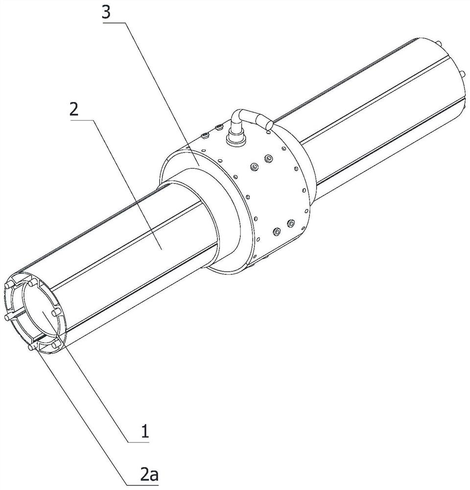
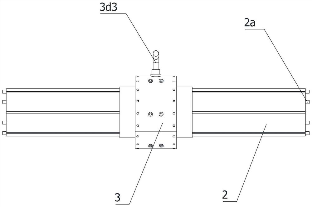
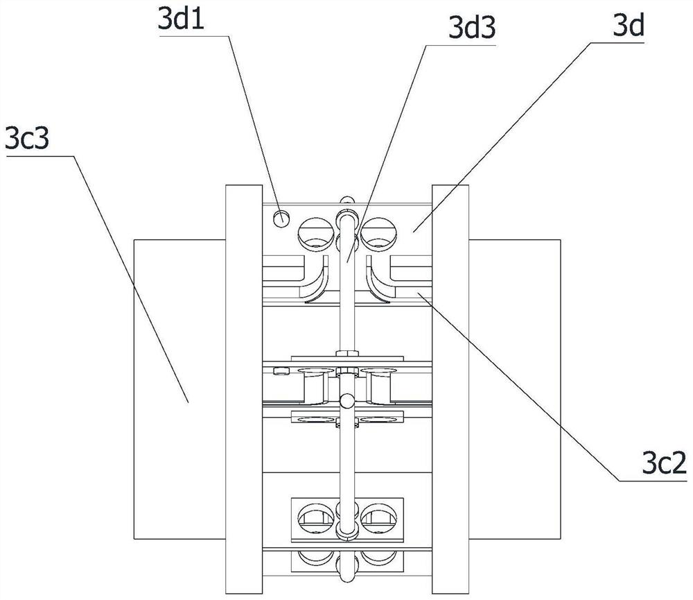
[0044] An electric heat tracing system for a polar pipeline, comprising a transmission pipeline 1, a thermal insulation pipeline 2 sleeved on the outside of the transmission pipeline 1, and a connection mechanism 3 connecting two adjacent thermal insulation pipelines 2, and the thermal insulation pipeline 2 is provided with There are several heating cables 2a equidistantly arranged around its axis, and the connecting mechanism 3 includes a connecting head 3a, a through hole 3b, two limit plates 3c, several mounting plates 3d and several for winding the heating cable 2a. The winding assembly 3e and several positioning assemblies 3f for fixing the end of...


PUM


Abstract

The invention relates to the technical field of electric heat tracing, in particular to a polar region pipeline electric heat tracing system which comprises a transmission pipeline, a heat preservation pipeline and a connecting mechanism, a plurality of heating cables are arranged on the heat preservation pipeline, and the connecting mechanism comprises a connector, a through hole, a limiting plate, a mounting plate, a winding assembly and a positioning assembly. The connecting head is arranged on the transmission pipeline in a sleeving mode through the through hole, the two ends of the connecting head are sleeved with the two heat preservation pipelines, the limiting plate limits the positions of the heat preservation pipelines, a containing space for the mounting plate, the winding assembly and the positioning assembly is provided, and the end of a heating cable penetrates through the limiting plate to be connected with the positioning assembly. Then the heating cable is fixed through the positioning assembly, the winding assembly drives the positioning assembly, the heating cable is wound on the positioning assembly, the later overhaul and maintenance of the heating cable are facilitated through the arrangement of the connector, the connection efficiency between heat preservation pipelines can be improved through the arrangement of the winding assembly and the positioning assembly, and the operation difficulty is reduced; and the burden of workers is reduced.

Description

technical field [0001] The invention relates to the technical field of electric heat tracing, in particular to a polar pipeline electric heat tracing system. Background technique [0002] The entire design of the LNG pipeline gallery is mainly to separate the different substances in the raw materials that require different boiling points, and all of them are transported in the form of liquid. Therefore, when the pipeline is transported, the operating temperature parameters are various, and various systems and processes are required. The long-term maintenance of the pipeline at a fixed temperature ensures that all impurities can be separated and the main product can safely reach the storage tank and be transported to its destination. Since the project is located in a polar climate and is in winter all the year round, it is a great challenge for the temperature control of all pipelines. Therefore, an electric heat tracing system is required to ensure that the polar pipelines a...

Claims


Application Information

Patent Timeline
Patent Type & Authority Applications(China)
IPC IPC(8): B65H75/28B65H54/74B65H54/72F17D1/18F17D5/00
CPCB65H75/285B65H54/74B65H54/72F17D1/18F17D5/00B65H2403/43B65H2701/34
Inventor 李林威童银杰杨琼陈世敏
Owner 舟山惠生海洋工程有限公司
Why Eureka
Try Eureka