
No.0 block supporting structure suitable for rigid frame bridge and construction method of No.0 block supporting structure

A technology for supporting structures and rigid-frame bridges, applied in bridges, bridge construction, bridge parts, etc., can solve the problem of time-consuming and labor-intensive bracket installation, and achieve the effect of saving materials, saving material consumption, and speeding up turnover.

Pending Publication Date: 2022-07-29
中建七局交通建设有限公司 +1
View PDF11 Cites 0 Cited by
  • Summary
  • Abstract
  • Description
  • Claims
  • Application Information

AI Technical Summary

Problems solved by technology

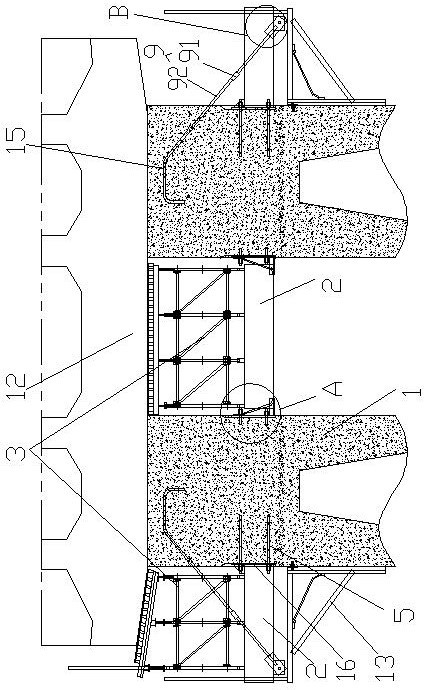
[0003] In view of the deficiencies in the above-mentioned background technology, the present invention proposes a support structure suitable for the No. 0 block of rigid frame bridges and its construction method, which solves the problem of time-consuming and labor-intensive installation of the bracket of No. 0 block in the prior art

Method used


Image

  • No.0 block supporting structure suitable for rigid frame bridge and construction method of No.0 block supporting structure
  • No.0 block supporting structure suitable for rigid frame bridge and construction method of No.0 block supporting structure
  • No.0 block supporting structure suitable for rigid frame bridge and construction method of No.0 block supporting structure

Examples


Embodiment 2

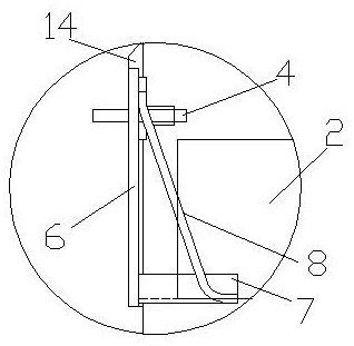
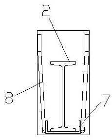
[0035] Example 2, which differs from Example 1 in that, as figure 2 and image 3 As shown, the support platform includes a steel plate one 6 detachably connected with the embedded bolts 4 and a channel steel 7 vertically connected to the lower part of the steel plate one 6. The outside of the channel steel 7 is also connected to the steel plate one 6 through a reinforcing connecting rod 8. The reinforcing connecting rod 8 includes a vertical section and a horizontal section fixed to the outside of the steel plate 1 6 and the channel steel 7 respectively, and the vertical section and the horizontal section are connected by a transition through inclined ends. The opening of the channel steel 7 is upward, and the two ends of the support beam 2 are respectively supported and placed in the opening of the channel steel 7 of a pair of supporting platforms.

Embodiment 3

[0036] Example 3, the difference from Example 1 is that, as Figure 4 and Figure 5 As shown, the connection mechanism includes a second steel plate 16 detachably connected to the threaded steel 5 , the support beam 2 is vertically fixed on the second steel plate 16 , and a reinforcing rib plate is also provided between the support beam 2 and the second steel plate 16 .

Embodiment 4

[0037] Embodiment 4, a construction method applicable to the support structure of the No. 0 block of a rigid frame bridge, including the above-mentioned support structure applicable to the No. 0 block of a rigid frame bridge, and also comprising the following steps:

[0038] S1. Construction of pre-embedded parts: During the construction of the top section of pier column 1 of a thin-walled hollow pier with double limbs, a certain size of groove is reserved, and the inner side of the pier column 1 is pre-embedded with pre-embedded nuts 4, and the outer side is pre-embedded with precision-rolled rebar. 5 and bending embedded parts 15;

[0039] S2, the processing of the support platform, that is, the components of the support platform include a steel plate 6, a channel steel 7 and a reinforcing connecting rod 8 to be welded and connected;

[0040] S3. The erection of the support system on the inner side of the pier column 1: including bolting the steel plate 1 6 of the supporting...


PUM


Abstract

The invention discloses a supporting structure suitable for a No.0 block of a rigid frame bridge and a construction method of the supporting structure. The supporting structure comprises an embedded rod piece embedded in a pier column, a supporting platform detachably connected to the embedded rod piece located on the inner side of the pier column, and a connecting mechanism detachably connected to the embedded rod piece located on the outer side of the pier column. The supporting platform and the connecting mechanism are each provided with a supporting beam used for supporting the disc buckle support. The mode that the supporting platform hoists and supports the supporting beams is adopted, the mounting and dismounting speed of the supporting beams is increased, and turnover materials are saved; the bent embedded parts and the combined connecting rod pieces form a cable-stayed structure to support the supporting beam, so that materials are saved; the 0 # block is poured twice, load grading is achieved, the load of the supporting structure is effectively shared, two mechanical structure models of lifting and cable-stayed supporting platform are established, stability and safety are guaranteed, and the material consumption is saved.

Description

technical field [0001] The invention relates to the technical field of bridges, in particular to a support structure for No. 0 block of a rigid frame bridge and a construction method thereof. Background technique [0002] With the continuous increase of investment in infrastructure by the state, the design of bridges is developing towards large spans. Due to the high beam height of rigid frame bridge No. 0, the cantilever end is overhanging longer, and the thin-walled hollow high pier No. The method of rack + bowl button bracket. However, for the 0# high pier, the installation of the bracket is time-consuming and laborious. The use of a large number of embedded parts makes it difficult to repair the appearance of the pier column, and the number of material turnover is small. Later, the high-altitude removal of the bracket increases the safety risk. SUMMARY OF THE INVENTION [0003] In view of the above-mentioned deficiencies in the background technology, the present inven...

Claims


Application Information

Patent Timeline
Patent Type & Authority Applications(China)
IPC IPC(8): E01D19/00E01D19/02E01D21/00
CPCE01D19/00E01D19/02E01D21/00
Inventor 吴靖江毋存粮杨伟姚兵景玉婷张浩齐宁宁张永方玉成潘铭岳盟袁金波杜乾武曹景博
Owner 中建七局交通建设有限公司
Learn More