Wind energy collecting system for expressway

A collection system, expressway technology, applied in the direction of wind power engine, wind power motor combination, cleaning method and appliance, etc., can solve problems such as flying stones excited by fan blades, potential safety hazards, low efficiency of wind energy utilization, etc.

Pending Publication Date: 2022-07-29
杨书彦
View PDF0 Cites 1 Cited by
  • Summary
  • Abstract
  • Description
  • Claims
  • Application Information

AI Technical Summary

Problems solved by technology

[0005] The purpose of the present invention is to provide a wind energy collection system for highways, to solve the problem that in the prior art proposed in the above background technology, the wind energy is directly blown away after passing through the fan blades, the utilization efficiency of wind energy is low, and there are flying stones on the highway Phenomenon, the rotating fan blades may excite flying stones, which poses a safety hazard

Method used


Image

  • Wind energy collecting system for expressway
  • Wind energy collecting system for expressway
  • Wind energy collecting system for expressway

Examples


specific Embodiment approach 1

[0036] Specific implementation mode 1: Please refer to Figure 1-7 , the present invention provides a technical solution: a wind energy collection system for expressways, comprising:

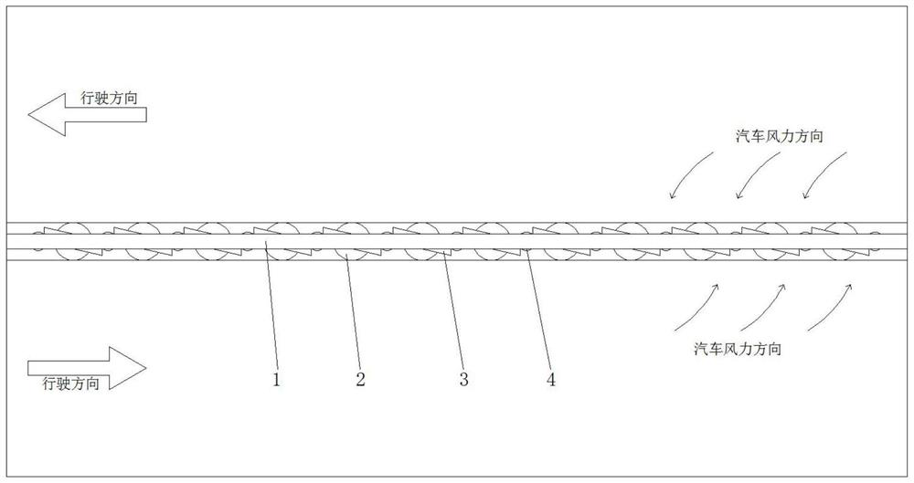
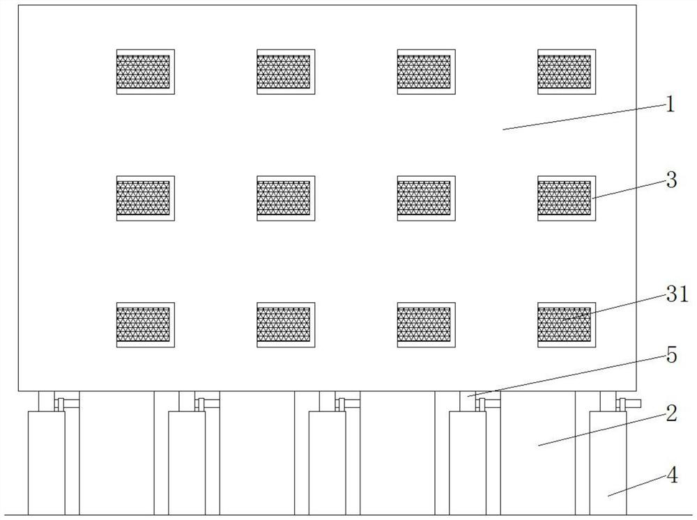
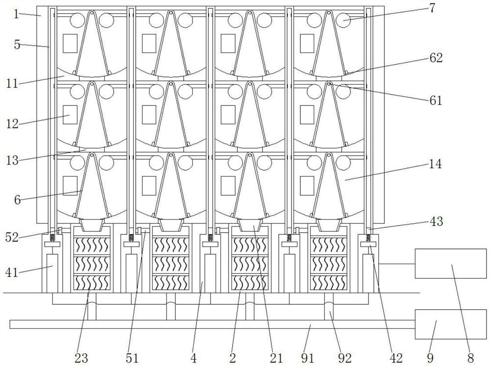
[0037] The isolation belt 1, a partition 11 is arranged inside the isolation belt 1, and an air inlet 12 is opened on the side of the isolation belt 1, and the air inlet 12 communicates with the cavity 14;

[0038] The gas storage cylinder 2 is installed at the bottom of the isolation belt 1, and an air storage cavity 24 is formed inside the gas storage cylinder 2, an electrode rod 22 is installed on the inner wall of the gas storage cylinder 2, and a film 23 is connected to the electrode rod 22;

[0039] The guide frame 3 is fixed on the outer surface of the isolation belt 1, and the inside of the guide frame 3 is provided with a blocking net 31, and the blocking net 31 blocks the air inlet 12;

[0040] The fixed seat 4, the fixed seat 4 and the gas storage cylinder 2 are alternately distribut...

specific Embodiment approach 2

[0049] Embodiment 2: This embodiment is a further limitation of Embodiment 1, such as image 3 and Figure 4 As shown, a communication hole 13 is opened in the middle of the partition plate 11. The partition plate 11 and the vertical rod 5 separate the inner space of the isolation belt 1 to form a plurality of cavities 14. The top surface of the partition plate 11 has an arc structure. The limiting plates 62 are symmetrically fixed on the top surfaces of the partitions 11 on both sides. The isolation belts 1 on the front and rear sides of the cavity 14 are provided with centrally symmetric air inlets 12. The partitions 11 are provided to enhance the stability of the isolation belt 1, and form The small cavity 14 enables the instantaneous wind force to fill the cavity 14 quickly, and the air inlets 12 are adapted to the direction of the wind force generated by the vehicles on both sides of the isolation belt 1 respectively.

specific Embodiment approach 3

[0050] Embodiment 3: This embodiment is a further limitation of Embodiment 2, such as figure 2 As shown, the communication hole 13 is connected to the upper and lower adjacent cavities 14, and an interface 21 is installed in the lowermost communication hole 13. The interface 21 has a trapezoidal structure. A baffle 6 with an inverted V-shaped structure is installed, the cavity 14 outside the baffle 6 is connected to the air inlet 12, the cavity 14 between the baffles 6 is communicated with the communication hole 13, and the communication hole 13 and the cavity 14 form an air duct , the interface 21 is wide at the top and narrow at the bottom to produce a compression effect on the wind force and speed up the wind speed.


PUM


Abstract

The invention discloses a wind energy collection system for an expressway, which comprises an isolation belt, a wind energy collection device, a wind energy collection device and a wind energy collection device, the air storage cylinder is mounted at the bottom of the isolation belt, and an air storage cavity is formed in the air storage cylinder; the flow guide frame is fixed to the outer surface of the isolation belt, and a blocking net is arranged in the flow guide frame; the fixing seats and the air storage cylinders are alternately distributed; the vertical rod is upwards inserted into the isolation belt; the top of the baffle plate is hung on the fixed shaft; the electric equipment is connected with the fixed seat through a wire; and the pressure relief equipment is connected with the air storage cylinder through a main pipeline and a branch pipeline. According to the wind energy collecting system for the expressway, wind power is guided into the cavity through the guide frame, the pressure in the cavity is increased, and therefore the included angle of the baffles is reduced, the wind power conveniently enters the air storage cylinders through the communicating holes, the wind power blows the films in the air storage cylinders, and the films rub against one another to generate electric energy.

Description

technical field [0001] The invention relates to the related technical field of expressway wind energy utilization, in particular to a wind energy collection system for expressways. Background technique [0002] Under the background of energy shortage, increasingly serious environmental problems, and consensus on the concept of sustainable development, more and more attention has been paid to how to make full use of solar energy, wind energy and other clean energy sources. When a vehicle is driving on a highway, airflow disturbance will occur on both sides of the vehicle , so as to generate wind, the direction of the wind depends on the direction of the car, and the magnitude of the wind energy depends on the speed of the car. [0003] At present, the common wind energy collection system for highways generally adopts a fan-blade power generation mechanism, which uses the wind energy generated by the driving of the car to drive the fan blades to rotate, and converts the wind e...

Claims


Application Information

Patent Timeline
IPC IPC(8): F03D9/11F03D9/17F03D9/46F03D5/06F03D80/00E01F7/02H02N1/04B01D46/10B01D46/76B08B7/02F17C5/06F17C13/04
CPCF03D9/11F03D9/17F03D9/46F03D5/06F03D80/00E01F7/025H02N1/04B01D46/10B08B7/02F17C5/06F17C13/04
Inventor 杨书彦
Owner 杨书彦
Why Eureka
Try Eureka