Bush identification device and identification method
A technology for identifying devices and bushings, which is applied to measuring devices, mechanical measuring devices, and mechanical devices, etc., can solve problems such as feeding errors, and achieve the effects of improving production efficiency, strong practicability, and simple structure
- Summary
- Abstract
- Description
- Claims
- Application Information
AI Technical Summary
Problems solved by technology
Method used
Image

Examples
Embodiment 1
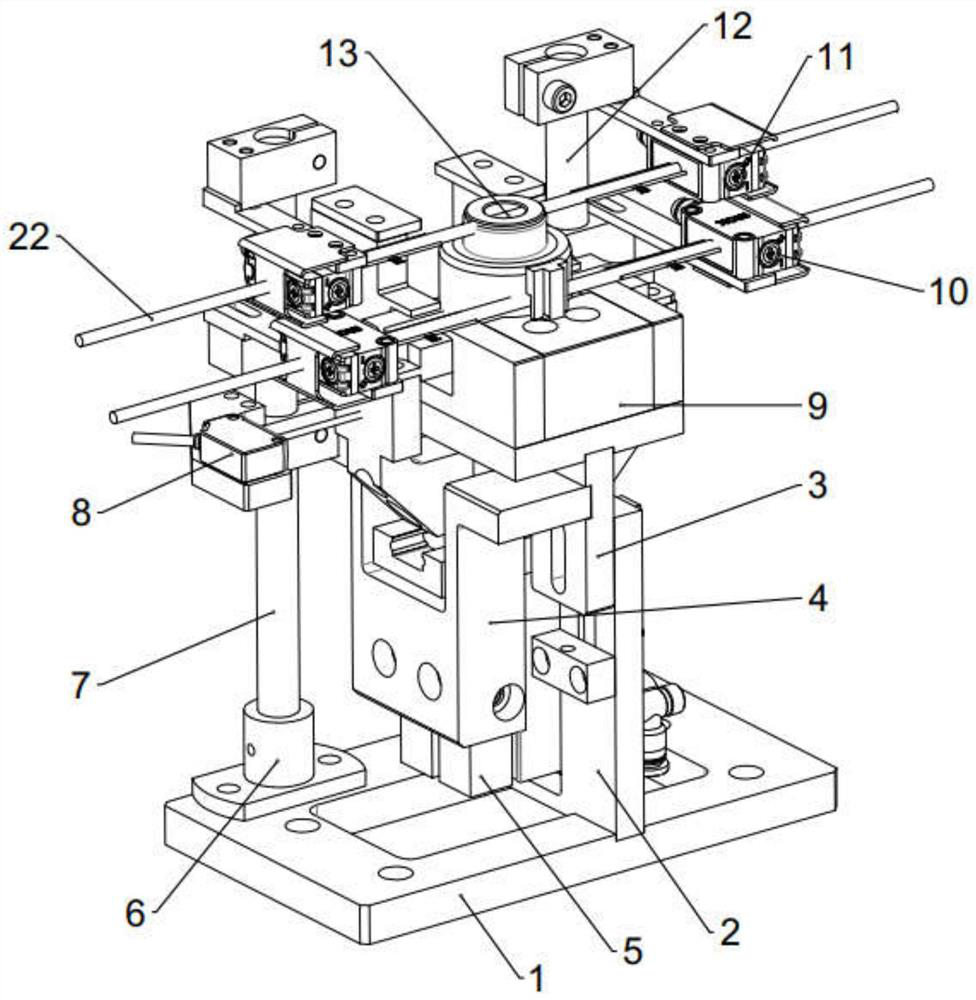
[0034] like figure 1 As shown, this embodiment provides a bushing identification device, including a base 1, a support mechanism, a diameter detection mechanism and a height detection mechanism.
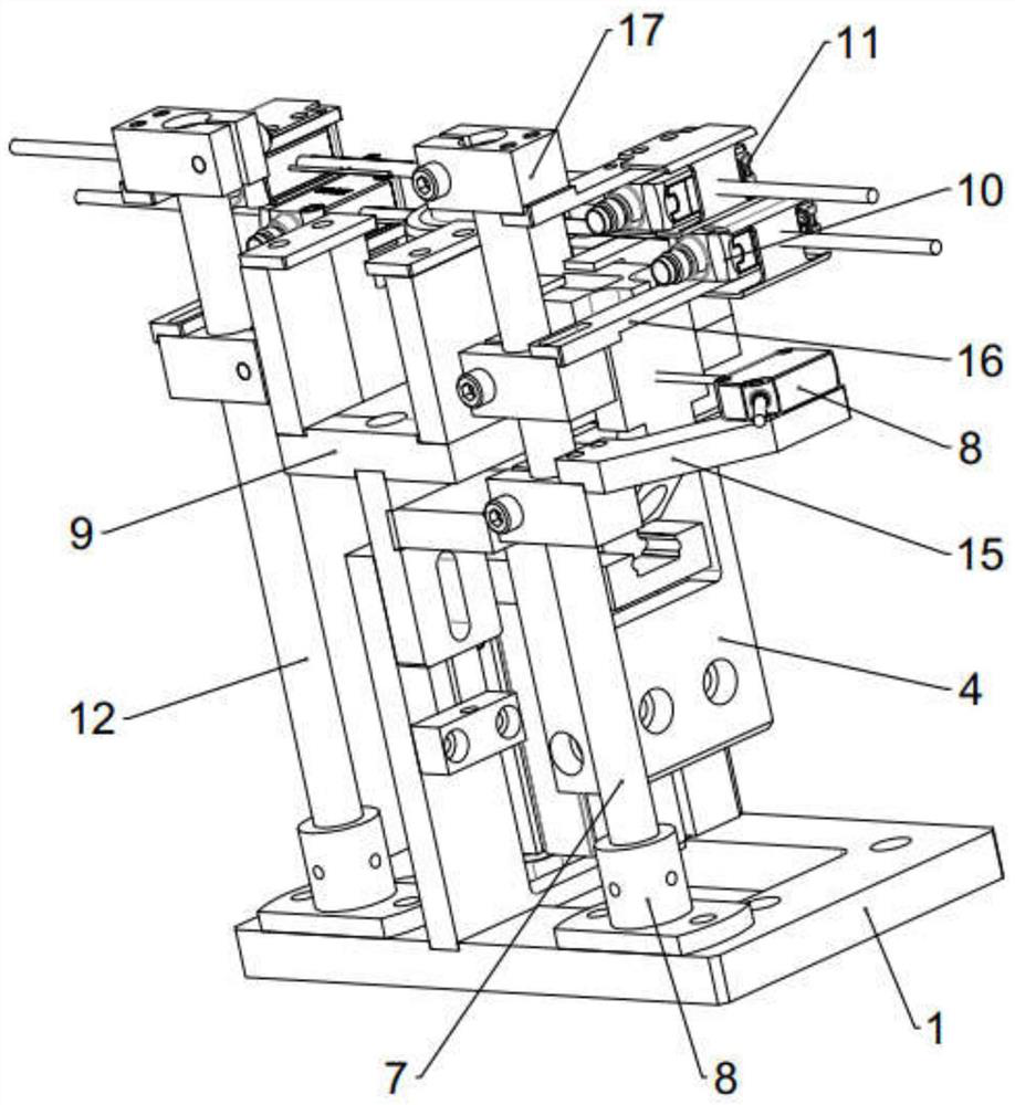
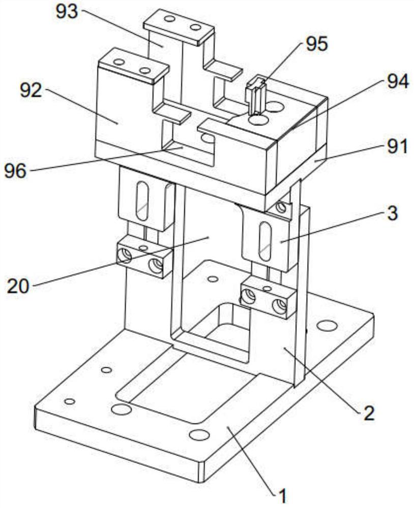
[0035] like Figure 1-3 As shown, the support mechanism is mounted on the base 1 for carrying the bushing 13 to be tested. Specifically, the support mechanism includes a lower support plate 2 that is fixedly connected to the base 1, an upper support plate 3 that is fixedly connected to the lower support plate 2, and a bearing seat 9 that is fixed to the top of the upper support plate 3; the lower support plate 2 is in a positive U shape, The upper support plate 3 is in an inverted U shape, and the lower support plate 2 and the upper support plate 3 are connected relative to each other to form a through groove 20 in the middle.
[0036] like image 3 As shown, the bearing seat 9 includes a bottom plate 91, a first flow channel side plate 92, a second flow channel side plate 93 and ...
Embodiment 2
[0041] This embodiment provides a method for lining recognition using the lining recognition device described in Embodiment 1, including the following steps:
[0042] The bushing 13 to be tested enters from the open ends of the first flow channel side plate 92 and the second flow channel side plate 93, and continues to advance to the arc surface of the L-shaped baffle plate 94;
[0043] The jaw cylinder 5 of the diameter detection mechanism drives the two jaws 19 to move, the slider 191 slides in the slide rail 18 when the jaws 19 move, and finally the grippers 193 of the two jaws 19 are clamped on the outer surface of the bushing 13 , The first laser sensor 8 measures the displacement of the jaws 19 to detect the diameter of the bushing 13, and if it does not meet the bushing diameter requirements of the station, an alarm prompts;
[0044] The second laser sensor 11 of the height detection mechanism detects the height of the bushing, and if it does not meet the bushing height...
Embodiment 3
[0046] like figure 1 and 2 As shown, this embodiment provides a bushing identification device, which includes the structure in the first embodiment, and also includes an in-position detection mechanism. The in-position detection mechanism is used to detect whether the bushing is in position. The three laser sensors 10 are a set of through-beam photoelectric sensors and are respectively mounted on the first guide column 7 and the second guide column 12 through the third mounting bracket 16 .
[0047] like Image 6 As shown, the structure of the third mounting bracket 16 is similar to that of the second mounting bracket 17 , including a second fixing block 161 fixed on the first guide column 7 by the fastening bolts 14 , and a second horizontal block 161 connected with the second fixing block 161 . The arm 162 and the protective cover 163 connected to the side of the second transverse arm 162 , the second transverse arm 162 is provided with a third mounting hole 164 for assemb...
PUM
 Abstract
Description
Claims
Application Information
 - R&D
- Intellectual Property
- Life Sciences
- Materials
- Tech Scout
- Unparalleled Data Quality
- Higher Quality Content
- 60% Fewer Hallucinations
Browse by: Latest US Patents, China's latest patents, Technical Efficacy Thesaurus, Application Domain, Technology Topic, Popular Technical Reports.
© 2025 PatSnap. All rights reserved.Legal|Privacy policy|Modern Slavery Act Transparency Statement|Sitemap|About US| Contact US: help@patsnap.com