Laser vision guided automatic welding track tracking system and method

A vision-guided and automatic tracking technology, applied in welding equipment, welding equipment, auxiliary welding equipment, etc., can solve the problems of low welding efficiency, poor versatility, and low flexibility

Inactive Publication Date: 2017-01-11
SOUTH CHINA UNIV OF TECH
View PDF5 Cites 54 Cited by
  • Summary
  • Abstract
  • Description
  • Claims
  • Application Information

AI Technical Summary

Problems solved by technology

[0006] The object of the present invention is to provide a laser vision-guided welding trajectory automatic tracking system, which aims to solve the problems of low welding efficiency, poor versatility, and low flexibility of welding robots in the "teaching and reproduction" type of welding, and at the same time solve the problems of existing automatic welding seams. Identify the problem of poor adaptive ability of the method and realize accurate automatic welding

Method used


Image

  • Laser vision guided automatic welding track tracking system and method
  • Laser vision guided automatic welding track tracking system and method
  • Laser vision guided automatic welding track tracking system and method

Examples


Embodiment 1

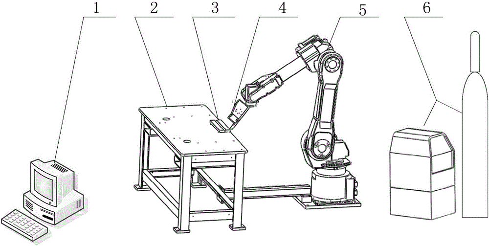
[0068] like figure 1 As shown, a laser vision-guided welding trajectory automatic tracking system includes an embedded industrial computer 1 with an image processing device, a laser vision sensor 4, a welding robot 5, supporting welding equipment 6 and a workpiece clamping workbench 2, and a workpiece 3 Fixed on the clamping workbench 2, the laser vision sensor 4 is installed on the welding torch in advance in the welding direction through the laser sensor fixing element, and the welding torch is installed on the end flange of the welding robot 5 through the welding torch fixing element. The sensor 4 and the welding torch change its position in space through the movement of each axis of the welding robot 5. The supporting welding equipment 6 provides energy and materials for welding, and the embedded industrial computer 1 is connected with the laser vision sensor 4. Based on the image recognition and tracking of objects acquired by the laser vision sensor 4 and the accurate de...

Embodiment 2

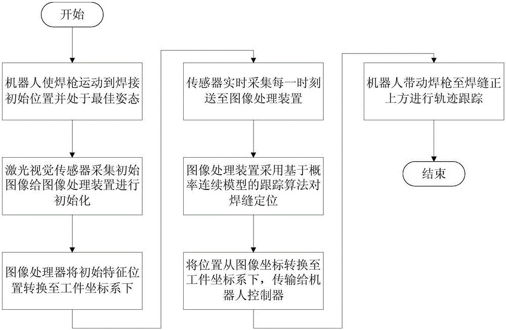
[0074] like image 3 Shown, a kind of welding track automatic tracking method based on the laser vision guidance of described system, comprises steps:

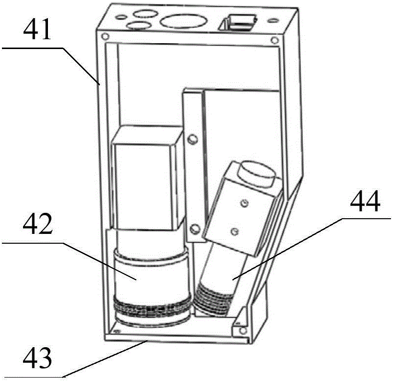
[0075] S1. Adjust the spatial position and posture of the welding robot 5 so that the welding gun with the fixed laser vision sensor 4 is in the initial welding position, and the laser line is within the field of view of the camera 42, and it is also necessary to ensure that during the continuous automatic welding seam recognition and tracking process, The workpiece will not interfere with the laser vision sensor 4;

[0076] S3, before the welding starts, the camera 42 in the laser vision sensor 4 first collects the characteristic fringe image and sends it to the image processing device, and performs initialization detection and positioning by calling the library function of the Halcon software to obtain the starting position of the weld seam;

[0077] S4, after the welding starts, the camera 42 of the laser vision sensor 4 c...


PUM

PropertyMeasurementUnit
wavelengthaaaaaaaaaa
transmittivityaaaaaaaaaa

Abstract

The invention discloses a laser vision guided automatic welding track tracking system which comprises an embedded type industrial personal computer with an image processing device, a laser vision sensor, a welding robot, matched welding equipment and a workpiece clamping workbench; the laser vision sensor is installed on a welding gun in an advanced parallel manner in the welding direction through a laser sensor fixing element; the welding gun is installed on a tail end flange disc of the welding robot through a welding gun fixing element; and the embedded type industrial personal computer is connected with the laser vision sensor through a circuit. The invention also discloses a laser vision guided automatic welding track tracking method. With adoption of the laser vision guided automatic welding track tracking system and method, without the process of teaching in advance, the welding production efficiency and the adaptive ability are improved through real-time detection and tracking; and meanwhile, the problem of tracking lag caused by advanced detection is prevented, and the problem that when a sensor is too near the welding gun, large noise of coupling feature images is caused by factors including strong arc light irradiation, high temperature and smoke dusts, thus the real time and the tracking accuracy of the system are restricted is solved.

Description

technical field [0001] The invention relates to the field of automatic tracking of welding trajectories, in particular to a system and method for automatic tracking of welding trajectories guided by laser vision. Background technique [0002] With the development of automation technology, welding robots have been widely used in the industrial field and have become the main welding automation equipment. At present, the robot welding method is mainly based on the "teaching and reproduction" mode, that is, the user guides the robot, and the robot automatically memorizes the position, posture, motion parameters, welding parameters, etc. of each movement taught during the guidance process, and automatically generates a A program that executes all operations continuously. After the teaching is completed, you only need to give the robot a start command, and the robot will repeat the expected welding work through the working program stored in the teaching program. However, due to ...

Claims


Application Information

Patent Timeline
Patent Type & Authority Applications(China)
IPC IPC(8): B23K37/02B23K9/127
CPCB23K9/1274B23K37/02
Inventor 邹焱飚周卫林王研博
Owner SOUTH CHINA UNIV OF TECH
Why Eureka
Try Eureka