Lithium battery voltage detection device for new energy automobile
A new energy vehicle, voltage detection technology, applied in the direction of measurement device, measurement of electricity, measurement of electric variables, etc., can solve the problems of inconvenient dust removal, affecting detection efficiency, affecting voltage detection effect, etc., to achieve good dust removal effect and detection effect. Good, large dust extraction effect
- Summary
- Abstract
- Description
- Claims
- Application Information
AI Technical Summary
Problems solved by technology
Method used
Image
Examples
Embodiment 1
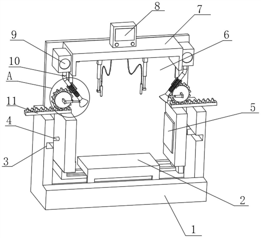
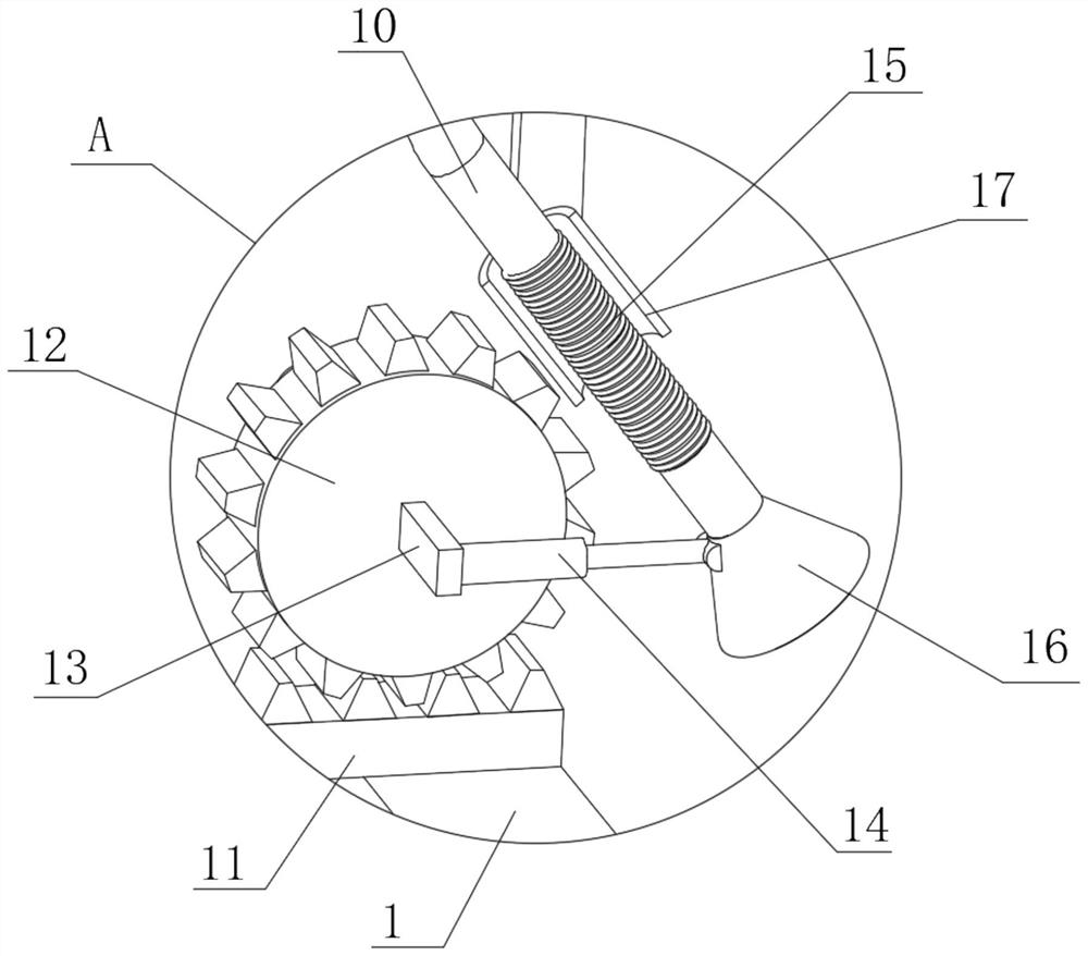
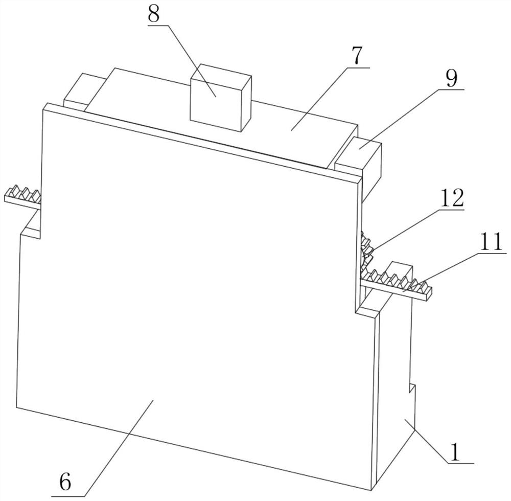
[0030] see Figure 1-Figure 4, the present invention provides a technical solution: a lithium battery voltage detection device for a new energy vehicle, comprising a base 1, the top of the base 1 is fixedly connected with a detection table 2, and one side inner wall of the base 1 is provided with a concave groove 3, A push rod 4 is fixedly connected to one inner wall of the concave groove 3, a clamping device 5 is fixedly connected to the side of the push rod 4 away from the concave groove 3, a vertical plate 6 is fixedly connected to the top of the base 1, and one side of the vertical plate 6 is fixed A top plate 7 is connected, a voltmeter 8 is fixedly connected to the top of the top plate 7, a fan box 9 is fixedly connected to the outer walls of both sides of the top plate 7, and an arc-shaped pipe 10 is fixedly connected to the bottom outer wall of the fan box 9, and the top of the clamping device 5 is fixedly connected. The outer wall is fixedly connected with a gear plat...
Embodiment 2
[0033] see Figure 5-Figure 6 As shown, on the basis of the first embodiment, the present invention provides a technical solution: the clamping device 5 includes a moving frame 501, and an outer wall of one side of the moving frame 501 is fixedly connected to the side of the push rod 4 away from the concave groove 3, wherein , when the push rod 4 moves, it is convenient to drive the moving frame 501 to move, the inner wall of one side of the moving frame 501 is fixedly connected with a buffer spring 1 502, and the side of the buffer spring 1 502 away from the inner wall of the moving frame 501 is fixedly connected with a buffer plate 503, the moving frame 501 A buffer spring two 504 is fixedly connected to the inner wall of one side of the buffer plate 503, and the limit plate 505 is fixedly connected to both ends of the buffer plate 503, and one side of the limit plate 505 is fixedly connected to one side of the buffer spring two 504. When the buffer plate 503 moves, it is co...
Embodiment 3
[0036] see Figure 7-Figure 8 As shown, on the basis of Embodiment 1 and Embodiment 2, the present invention provides a technical solution: a motor 18 is fixedly connected to the inner wall of one side of the top plate 7, and a screw rod 19 is rotatably connected to one side of the motor 18, and the screw rod 19 A rotating block 1 20 is fixedly connected to the side away from the motor 18 , a telescopic cylinder 21 is fixedly connected to the side of the rotating block 20 away from the screw 1 19 , and a screw 26 is rotatably connected to the side of the top plate 7 away from the motor 18 , and the screw 1 19 It is opposite to the thread direction of the second screw 26. When the screw one 19 and the second screw 26 rotate at the same time, due to the opposite thread direction, the moving direction of the screw block one 22 on the outer wall is opposite, and the screw one 19 and the second screw 26 move in the opposite direction. The outer wall is respectively screwed with a t...
PUM
 Abstract
Description
Claims
Application Information
 - R&D
- Intellectual Property
- Life Sciences
- Materials
- Tech Scout
- Unparalleled Data Quality
- Higher Quality Content
- 60% Fewer Hallucinations
Browse by: Latest US Patents, China's latest patents, Technical Efficacy Thesaurus, Application Domain, Technology Topic, Popular Technical Reports.
© 2025 PatSnap. All rights reserved.Legal|Privacy policy|Modern Slavery Act Transparency Statement|Sitemap|About US| Contact US: help@patsnap.com


