
Control circuit and control method for liquid crystal pixel

A liquid crystal pixel and control circuit technology, applied to static indicators, instruments, etc., can solve problems such as design difficulties and cost increases, and achieve the effects of fast speed, reduced driving ability requirements, and extended backlight lighting time

Pending Publication Date: 2022-07-29
CHENGDU JIUTIAN HUAXIN TECH CO LTD
View PDF0 Cites 0 Cited by
  • Summary
  • Abstract
  • Description
  • Claims
  • Application Information

AI Technical Summary

Problems solved by technology

For the backlight, it is necessary to distinguish and display by time and area, and this problem will lead to huge design difficulties and cost increases

Method used


Image

  • Control circuit and control method for liquid crystal pixel
  • Control circuit and control method for liquid crystal pixel
  • Control circuit and control method for liquid crystal pixel

Examples


Embodiment 1

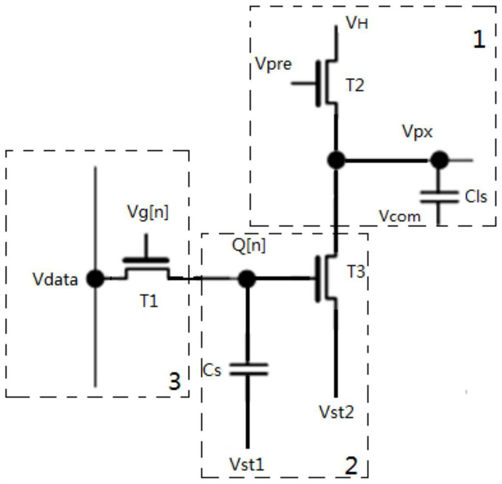
[0057] Embodiment 1 of the present invention provides a circuit for liquid crystal pixels, such as figure 1 As shown, it includes a preset charging module 1, a second-order programming module 2 and a first-order programming module 3 that are connected in sequence;

[0058] The preset charging module 1 is used to charge the liquid crystal pixel capacitor through a high level, and preset the liquid crystal pixel to a high level state;

[0059] The second-order programming module 2 discharges the preset charging module 1 according to the programming data of the first-order programming module 3, so that the electric charge reaches the maintenance voltage required by the liquid crystal pixel to display the image;

[0060] The first-order programming module 3 receives and saves the electric charge transmitted from the external control unit for the display of the next frame of image;

[0061] In this way, with the above structure, the liquid crystal pixel capacitor of the preset cha...

Embodiment 2

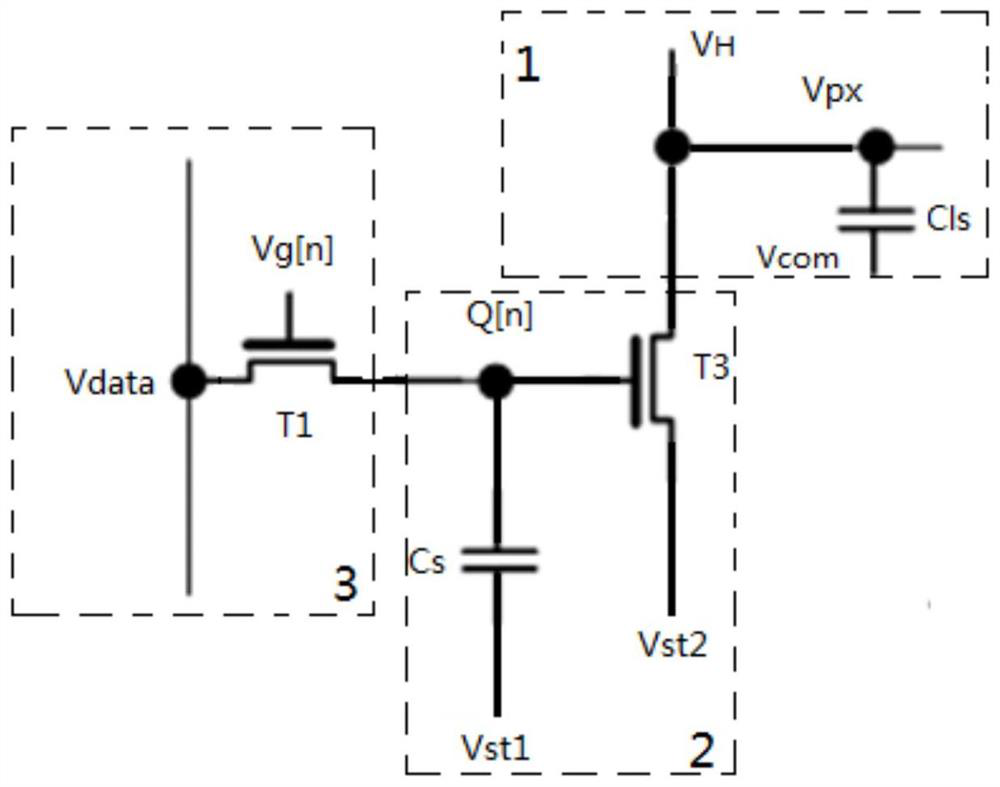
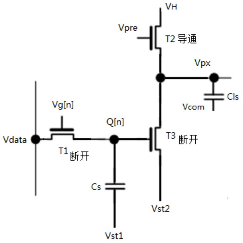
[0096] Embodiment 2 of the present invention provides a control method for liquid crystal pixels, which applies the control circuit for liquid crystal pixels described in Embodiment 1, such as Figure 9 and Figure 12 shown, the specific steps are as follows:

[0097] S1, charge the liquid crystal pixel capacitor through a high level, and preset the liquid crystal pixel to a high level state; specifically:

[0098] Preset all the liquid crystal pixels that make up the LCD screen to a high level at one time and synchronously through a high level;

[0099] S2, programming through the second-order programming module to discharge the preset charging module so that the charge reaches the maintenance voltage required by the liquid crystal pixel to display the image; specifically:

[0100] Through the cooperation of the first synchronization signal Vst1 and the second synchronization signal Vst2, the third transistor T3 is turned on to discharge the liquid crystal pixel capacitor C...


PUM


Abstract

The invention discloses a control circuit and a control method for liquid crystal pixels, and the control circuit for the liquid crystal pixels comprises a preset charging module, a second-order programming module and a first-order programming module which are connected in sequence, the method comprises the following steps: firstly, charging a preset charging module; programming the preset charging module through a second-order programming module to enable the voltage of the preset charging module to reach the maintaining voltage required by the liquid crystal screen to display the image; and finally, when the liquid crystal screen displays the current image under the maintaining voltage, the first-order programming module displays the storage electric quantity for the next frame of image. When the current image is displayed, the electric quantity required for displaying the next frame of image is prepared in advance, so that the time is saved through the mode of jointly displaying and storing in advance, and the phenomena of color disorder and picture tearing caused by time delay from the first row to the last row in a grid scanning driving mode of the liquid crystal display are effectively improved.

Description

technical field [0001] The invention belongs to the technical field of liquid crystal screen display, and in particular relates to a control circuit and a control method for liquid crystal pixels. Background technique [0002] The display principle of an ordinary liquid crystal screen is: after each line of thin film transistors in the display device of the liquid crystal screen is turned on by the gate circuit, the source circuit is responsible for charging. During this period, the backlight on the back of the liquid crystal screen is responsible for providing light source illumination, and the liquid crystal Each pixel is responsible for the passing of light and the size of the number of passing light, so as to form a color image with the cooperation of color filters; it is characterized by the presence of color filters, and the backlight is always on. [0003] With the advancement of technology, the principle of time-series field display liquid crystal has been proposed. ...

Claims


Application Information

Patent Timeline
IPC IPC(8): G09G3/36
CPCG09G3/3648G09G2320/0257
Inventor 张锦
Owner CHENGDU JIUTIAN HUAXIN TECH CO LTD
Learn More