[0023] The technical solutions in the embodiments of the present invention will be clearly and completely described below with reference to the accompanying drawings in the embodiments of the present invention. Obviously, the described embodiments are only a part of the embodiments of the present invention, not all of the embodiments. Based on the embodiments of the present invention, all other embodiments obtained by those of ordinary skill in the art without creative work fall within the protection scope of the embodiments of the present invention.
[0024] It should be noted that all directional indications (such as up, down, left, right, front, back, etc.) in the embodiments of the present invention are only used to explain the relationship between various components under a certain posture (as shown in the accompanying drawings). The relative positional relationship, the movement situation, etc., if the specific posture changes, the directional indication also changes accordingly.
[0025] In addition, in the embodiments of the present invention, descriptions such as “first”, “second”, etc. are only used for description purposes, and should not be interpreted as indicating or implying their relative importance or implicitly indicating the number of technical features indicated. . Thus, a feature delimited with "first", "second" may expressly or implicitly include at least one of that feature. In the description of the embodiments of the present invention, "plurality" means at least two, such as two, three, etc., unless otherwise expressly and specifically defined.
[0026] In the embodiments of the present invention, unless otherwise expressly specified and limited, the terms "connection" and "fixed" should be understood in a broad sense. For example, "fixed" may be a fixed connection, a detachable connection, or an integrated It can be a mechanical connection or an electrical connection; it can be a direct connection or an indirect connection through an intermediate medium, and it can be the internal communication between two elements or the interaction relationship between the two elements, unless otherwise clearly defined. For those of ordinary skill in the art, the specific meanings of the above terms in the embodiments of the present invention can be understood according to specific situations.
[0027] In addition, the technical solutions between the various embodiments of the present invention can be combined with each other, but must be based on the realization by those of ordinary skill in the art. When the combination of technical solutions is contradictory or cannot be achieved, it should be considered that the combination of technical solutions It does not exist and is not within the protection scope required by the embodiments of the present invention.
[0028] During the use of electric vehicles, users have higher and higher requirements for fast charging. In order to achieve fast high-power charging and avoid the cable temperature being too high during the charging process, it is a common choice to increase the cable diameter. However, increasing the wire diameter will lead to higher costs, and will also lead to an increase in the weight of the cable, resulting in an increase in the volume of ancillary products such as charging guns, making the entire charging device thicker and heavier. Therefore, the use of small wire diameter and lightweight liquid-cooled cables to reduce the cable temperature has become a popular solution for high-power charging. However, the wire diameter of the existing liquid-cooled cables is still relatively large, and there is still room for improvement to further meet the demand for miniaturization of products.
[0029] In view of this, the embodiments of the present invention provide a small wire diameter high power charging cable structure and a charging device, using the structure between the inner wall and the outer wall of the insulating sheath to form a liquid cooling channel, and contact the conductor with the inner wall of the insulating sheath. , using the flow of cooling liquid between the inner wall and outer wall of the insulating sheath to take away the heat on the surface of the conductor, dissipate heat in time, cancel the separate setting of the liquid cooling pipe, and further reduce the wire diameter and weight of the liquid cooling cable.
[0030] In order to better understand the above technical solutions, the above technical solutions are described in detail below with reference to the accompanying drawings.
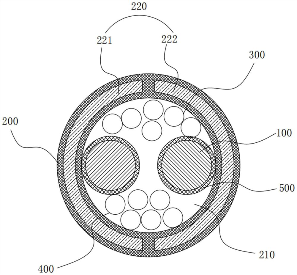
[0031] like figure 1 As shown, the structure of the small-diameter high-power charging cable proposed by the embodiment of the present invention, the small-diameter high-power charging cable structure includes:
[0032] conductor 100; and
[0033] The insulating sheath 200 forms a cavity 210 for accommodating the conductor 100 inside, the insulating sheath 200 has an inner wall facing the cavity 210 and an outer wall facing away from the cavity 210, and the insulating sheath 200 is formed between the inner wall and the outer wall for cooling liquid The flowing liquid flow channel 220, conductor 100, insulating sheath 200 and the extending direction of liquid flow channel 220 are parallel.
[0034] In the technical solution adopted in this embodiment, the conductor 100 is used to electrically connect with an external charging device to conduct the circuit. After the circuit is conducted, the conductor 100 will generate a large amount of heat. For this purpose, an insulating sheath 200 is provided. On the one hand, the conductor 100 can be covered by the cavity 210 of the insulating sheath 200, so as to achieve effective protection for the conductor 100, avoid scratching the conductor 100 and affect the normal use, and also prevent On the other hand, a liquid flow channel 220 is set between the inner wall and the outer wall of the insulating sheath 200, and the liquid flow channel 220 is filled with cooling liquid, and the cooling liquid can pass through the liquid flow channel 220. flow within. The outer surface of the conductor 100 is in contact with the inner wall of the insulating sheath 200, so when the liquid-cooled cable is in use, the flow of the cooling liquid in the liquid flow channel 220 can take away the heat on the surface of the conductor 100, thereby The conductor 100 is dissipated in time, so that the temperature of the conductor 100 is within a safe range, so as to avoid safety hazards caused by the overheating of the conductor 100, and improve the heat dissipation effect of the liquid-cooled cable. Moreover, in the technical solution proposed by the present invention, the arrangement of the liquid cooling pipe is cancelled, and the liquid flow channel 220 is designed by using the structure between the inner wall and the outer wall of the insulating sheath 200, so as to realize the full utilization of the structure of the insulating sheath 200 and reduce the The overall weight of the liquid-cooled cable improves the overall space effect, reduces the wire diameter of the liquid-cooled cable, and meets the design requirements for compact and miniaturized products.
[0035]Specifically, the structure of the small-diameter high-power charging cable proposed in this embodiment can be applied to high-power charging equipment, such as a charging gun or a charging stand, and the small-diameter high-power charging cable structure may include an insulating sheath 200 . and conductor 100.
[0036] The conductor 100 is the main wire of the small-diameter high-power charging cable structure. The conductor 100 may be a single wire or a bundle of multiple wires, preferably a power conductor 100 is formed by a bundle of several wires to ensure that the power conductor 100 has a strong current-carrying capacity. In order to avoid loosening of multiple wire bundles, braid can be used to fix them.
[0037] The insulating sheath 200 is wrapped on the outside of the conductor 100. It can be understood that the insulating sheath 200 is a hollow structure, that is, a cavity 210 for accommodating the conductor 100 is formed, and the conductor 100 is arranged in the cavity 210, so as to utilize the cavity 210 conveniently covers the conductor 100, which can prevent other components from scratching the conductor 100 and affect normal use, realize the protection of the conductor 100 by the insulating sheath 200, and also prevent the conductor 100 from leaking and causing accidental injury to personnel. In order to further reduce the wire diameter of the liquid-cooling cable, the liquid-cooling tube is eliminated in this embodiment, and the liquid-cooling channel is formed by the self-structure between the inner wall and the outer wall of the insulating sheath 200 , that is, the liquid-cooled The channel is arranged between the inner wall and the outer wall of the insulating sheath 200, and does not occupy additional space, and the structural part between the inner and outer walls of the insulating sheath 200 is fully utilized, thereby reducing the overall weight of the liquid-cooled cable and improving the overall space. Effectively, the wire diameter of the liquid-cooled cable is reduced, which meets the design requirements of compact and miniaturized products. Moreover, the outer surface of the conductor 100 is in contact with the inner wall of the insulating sheath 200. When the cooling liquid flows in the liquid cooling channel, it can effectively take away the heat on the surface of the conductor 100, dissipate heat to the conductor 100 in time, and improve the cooling effect of the liquid cooling cable. .
[0038] It should be pointed out that the insulating sheath 200 can be made of insulating material, and can be made of any one of PVC, TPE, TPU and rubber materials, and its shape can be set to a cylindrical shape, which is convenient to form a space for accommodating the conductor 100. cavity 210, thereby simplifying the production process, improving the production efficiency and reducing the production cost. The cooling liquid in this embodiment can be an insulating liquid with good thermal conductivity, for example, any one of transformer oil, capacitor oil, cable oil, silicone oil or mineral oil can be used.
[0039] Further, refer to figure 1 , in an embodiment of the present invention, the liquid flow channel 220 includes a liquid inlet channel 221 and a liquid outlet channel 222, and the liquid inlet channel 221 and the liquid outlet channel 222 are respectively independently provided between the inner wall and the outer wall of the insulating sheath 200. The liquid channel 221 and the liquid outlet channel 222 are connected by an external pipeline to form a cooling circuit, wherein the liquid inlet channel 221 and the liquid outlet channel 222 are respectively provided with at least one conductor 100 correspondingly.
[0040] In the technical solution adopted in this embodiment, the liquid flow channel 220 can be divided into a liquid inlet channel 221 and a liquid outlet channel 222. The liquid inlet channel 221 and the liquid outlet channel 222 are arranged in parallel, and a connecting device can be connected outside the insulating sheath 200. Communication is made to form a circulating circuit in which the coolant flows. By arranging the liquid inlet channel 221 and the liquid outlet channel 222, the different conductors 100 can be dissipated separately, so as to avoid the local high temperature of the liquid-cooled cable caused by the heat dissipation of all the conductors 100 through the liquid inlet channel 221 or the liquid outlet channel 222, thereby Improve the uniformity of heat dissipation. It should be pointed out that the number of conductors 100 can be odd or even. When an odd number of conductors 100 is provided, the number of conductors 100 to be cooled corresponding to the liquid inlet channel 221 is A, and the liquid outlet channel 222 corresponding to the number of conductors 100 to be cooled. The number of conductors 100 to be cooled is B, and A is one more than B, or A is one less than B; when an even number of conductors 100 is provided, the conductors 100 are evenly distributed between the liquid inlet channel 221 and the liquid outlet channel 222 .
[0041] It should be pointed out that if the liquid inlet channel 221 or the liquid outlet channel 222 is provided with a plurality of conductors 100 correspondingly, the plurality of conductors 100 may be in contact with the inner wall of the insulating sheath 200 respectively; it may also be one of the conductors 100 and the insulating sheath 200. The inner wall of the other conductors 100 is in contact with the above-mentioned conductors 100 . That is to say, the specific contact manner of the plurality of conductors 100 and the inner wall of the insulating sheath 200 is not limited in this embodiment.
[0042] Further, in an embodiment of the present invention, the liquid inlet channel 221 and the liquid outlet channel 222 are symmetrically arranged with respect to the cavity 210 .
[0043] In the technical solution adopted in this embodiment, in order to further improve the uniformity of heat dissipation of the liquid cooling cable, the liquid inlet channel 221 and the liquid outlet channel 222 are symmetrically arranged with respect to the cavity 210 , that is, the liquid inlet channel 221 and the liquid outlet channel 221 are arranged symmetrically with respect to the cavity 210 . The area size, position and shape of the channel 222 are the same, so that each position inside the liquid-cooled cable can obtain the same cooling effect provided by the cooling liquid, thereby ensuring the uniformity of heat dissipation on the outer surface of the conductor 100 and avoiding the occurrence of Local high temperature affects normal use.
[0044] Further, in an embodiment of the present invention, the cross-sections of the liquid inlet channel 221 and the liquid outlet channel 222 are arc-shaped, respectively.
[0045] In the technical solution adopted in this embodiment, the cross-sections of the liquid inlet channel 221 and the liquid outlet channel 222 are arc-shaped respectively, which can make full use of the structure between the inner and outer walls of the insulating sheath 200, so that the liquid inlet channel 221 and the liquid outlet channel The channel 222 has a larger cross-sectional area and can be filled with more cooling liquid. The cooling liquid has more cooling capacity, and can take away more heat from the surface of the conductor 100 when flowing, thereby improving the heat dissipation effect.
[0046] Further, in an embodiment of the present invention, the material of the insulating sheath 200 is an explosion-proof material.
[0047] In the technical solution adopted in this embodiment, when the liquid-cooled cable is energized and used, the insulating sheath 200 made of explosion-proof material can be used to improve the compressive resistance of the insulating sheath 200, so that the insulating sheath 200 can withstand the internal The pressure generated by the cooling liquid due to high temperature can prevent the insulating sheath 200 from bursting under high temperature and high pressure conditions, improve the safety of use, and prolong the service life of the liquid-cooled cable. In this embodiment, the explosion-proof material can be cross-linked PE (polyethylene), which has good insulation, heat resistance, and chemical resistance. Effectively withstand the pressure of the cooling liquid in the insulating sheath 200 due to high temperature, and prevent the insulating sheath 200 from bursting.
[0048] Further, in an embodiment of the present invention, the outer surface of the conductor 100 is covered with an insulating layer 500 .
[0049] In the technical solution adopted in this embodiment, the insulating layer 500 provided on the outer surface of the conductor 100 can prevent accidental short circuit when the conductor 100 is connected to the external charging device, and can also prevent the conductor 100 from being in contact with the cavity 210. Accidental short-circuit of other conductors and wires can realize the stable transmission of high-power electric energy and ensure the normal use of charging equipment.
[0050] Further, in an embodiment of the present invention, the small wire diameter high power charging cable structure further includes a ground wire 400 disposed in the cavity 210 , and the ground wire 400 is in contact with the inner wall of the insulating sheath 200 .
[0051] In the technical solution adopted in this embodiment, the ground wire 400 is also called a safety return wire, and the high voltage can be directly transferred to the ground in case of danger, so as to avoid electric shock to the user. It can be understood that when the liquid-cooled cable is working normally, the ground wire 400 does not carry current, and the function of the ground wire 400 is transient. The trip cuts off the power supply, and the cooling system consisting of the coolant and liquid flow passages also stops working. In this embodiment, the ground wire 400 may include a ground wire conductor and a ground wire insulation layer, the ground wire insulation layer is wrapped around the outer periphery of the ground wire conductor, wherein the ground wire conductor is used to transfer high-voltage current to the ground, and the ground wire Insulation prevents accidental shorting of ground conductors and other conductors.
[0052] Further, in an embodiment of the present invention, the ground wire 400 includes a plurality of independently arranged sub-wires, and the plurality of sub-wires are respectively and independently arranged in the cavity 210 .
[0053] In the technical solution adopted in this embodiment, the grounding wire 400 includes a plurality of independently arranged sub-wires, that is, the grounding wire 400 is divided into a plurality of sub-wires, so that the wire diameter of each sub-wire is relatively small , when arranging, each sub-wire occupies a relatively small space in the liquid-cooled cable, which can make full use of the space in the cavity 210, and can be flexibly arranged in the liquid-cooled cable, improving the sub-wire and other cables. The convenience in arrangement makes the space utilization in the cavity 210 more reasonable and the overall connection more compact.
[0054] Further, in an embodiment of the present invention, the small-diameter high-power charging cable structure further includes other wire cores 300 arranged in the cavity 210 . At least one of the conductors is in contact with the inner wall of the insulating sheath 200 , and the ground wire 400 and the other cores 300 are arranged on opposite sides of the conductor 100 .
[0055] In the technical solution adopted in this embodiment, the other wire cores 300 are used to electrically connect low-power devices, and may be cables with an insulating layer or bare cables. The other cores 300 are fixed within the insulating layer. A plurality of other wire cores 300 will generate heat when in use, and at least one other wire core 300 is in contact with the inner wall of the insulating sheath 200 , and cooling liquid can be used for cooling, thereby improving the heat dissipation capability of the liquid-cooled cable. In addition, the ground wire 400 and the other wire cores 300 are disposed on opposite sides of the conductor 100 , which can make full use of the idle space in the cavity 210 and make the space utilization in the cavity 210 more reasonable.
[0056] An embodiment of the present invention also provides a charging device, which includes the above small-diameter high-power charging cable structure. Specifically, the specific structure of the small-diameter high-power charging cable structure refers to the above-mentioned embodiment. The device adopts all the technical solutions of the above-mentioned embodiments, and therefore at least has all the beneficial effects brought about by the technical solutions of the above-mentioned embodiments, which will not be repeated here.
[0057] The above descriptions are only preferred embodiments of the present invention, and are not intended to limit the patent scope of the embodiments of the present invention. Under the inventive concept of the embodiments of the present invention, equivalent structural transformations are made by using the descriptions and accompanying drawings of the embodiments of the present invention. , or direct/indirect applications in other related technical fields are included in the scope of patent protection of the embodiments of the present invention.