Computer nixie tube packaging device

A packaging device, digital tube technology, applied in packaging recycling, transportation and packaging, conveyor objects, etc., can solve the problems of dust removal, increase labor intensity, and digital tube sticking and falling off, and achieve the effect of ensuring cleanliness and improving work efficiency.

Active Publication Date: 2022-07-29
山东工程技师学院
View PDF5 Cites 0 Cited by
  • Summary
  • Abstract
  • Description
  • Claims
  • Application Information

AI Technical Summary

Problems solved by technology

[0005] Aiming at the deficiencies in the prior art, the present invention provides a computer digital tube packaging device, which solves the problem that the existing computer digital tube packaging device is inconvenient to automatically remove the dust on the shell during packaging, and is easy to integrate with the digital tube after glue injection. When the tube is pasted, it will fall off, which will lead to the appearance of defective products, and there are many manual operation steps that not only need to squeeze the glue but also continue to move it by hand, which increases the labor intensity and reduces the work efficiency of the digital tube package.

Method used


Image

  • Computer nixie tube packaging device
  • Computer nixie tube packaging device
  • Computer nixie tube packaging device

Examples


Embodiment 1

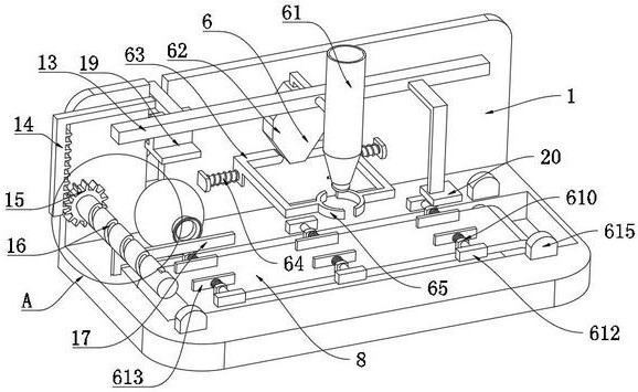
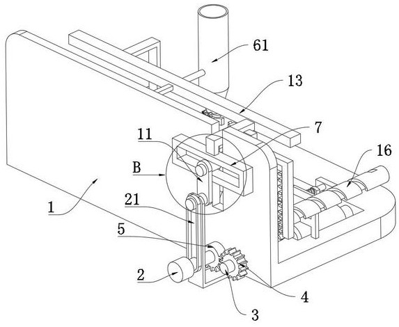
[0037] see figure 1 and image 3 and Figure 5, including the base plate 1, the rear end surface of the base plate 1 is fixedly connected with the drive motor 2 through the mounting plate 21, the output shaft of the drive motor 2 is fixedly connected with the half gear 5 through one end of the mounting plate 21, and the inner cavity wall of the base plate 1 is symmetrically rotated and connected with a Transmission shaft 3, a conveyor belt 8 is connected to the outer wall of the transmission shaft 3, and a gear 4 is fixedly connected to one end of the transmission shaft 3 through the rear end surface of the base plate 1. Mechanism 6, the rear end surface of the base plate 1 is slidably connected with the sliding frame 7 through the sliding rod 13, the rear end surface of the mounting plate 21 is connected with the support shaft 9 through rotation, and the outer wall of the output shaft of the drive motor 2 is connected with the support shaft 9 through the belt 10. The front ...

Embodiment 2

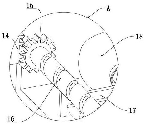
[0040] see Figure 1 to Figure 2 , the left side wall of the sliding rod 13 is fixedly connected with the rack 14, the front end surface of the base plate 1 is rotatably connected with a spiral groove rod 16, and the groove plate of the spiral groove rod 16 is slidably connected with the cleaning brush plate 17 through the slider, and the spiral groove rod 16 The outer wall of the base plate 1 is fixedly connected with a gear ring 15, the gear ring 15 is engaged with the rack 14, the cleaning brush plate 17 is slidingly connected with the upper end surface of the base plate 1, and the lower end surface of the sliding rod 13 is fixedly connected with a pressure rod 19.

[0041] During operation, through the cooperation of the rack 14, the ring gear 15, the spiral groove rod 16, and the cleaning brush plate 17, when the sliding rod 13 descends, the rack 14 will be driven to descend synchronously, and the gear ring 15 will be engaged to drive the spiral groove rod 16 to rotate. W...

Embodiment 3

[0043] see figure 1 and Image 6 and Figure 7 and Figure 8 , the extrusion limit mechanism 6 includes a rubber tube 61 and a diamond-shaped block 62. The front end surface of the sliding rod 13 is fixedly connected with a rubber tube 61, and the lower end surface of the sliding rod 13 is fixedly connected with a diamond-shaped block 62. The front end surface of the base plate 1 is symmetrically slidingly connected with The guide rod 63, one end of the guide rod 63 close to each other is attached to the outer wall of the diamond block 62, the front end surface of the base plate 1 is fixedly connected with the outer wall of the guide rod 63 through the spring telescopic rod 64, and the two guide rods 63 are fixedly connected to each other at one end of the guide rod 63 close to each other. Squeeze plate 65, the outer wall of the rubber tube 61 close to the lower part is symmetrically and fixedly connected with a convex block 67, the side wall of the convex block 67 is rotata...


PUM


Abstract

The invention relates to the technical field of computer nixie tubes, in particular to a computer nixie tube packaging device which comprises a substrate, the rear end face of the substrate is fixedly connected with a driving motor through a mounting plate, and the end, penetrating through the mounting plate, of an output shaft of the driving motor is fixedly connected with a half gear. The computer nixie tube packaging device comprises a base plate, transmission shafts are symmetrically and rotatably connected to the inner cavity wall of the base plate, a sliding shaft is rotatably connected to the end, away from a supporting shaft, of a rotating plate, the front end face of the sliding shaft is slidably connected with an inner cavity of a sliding frame, and a balloon is installed on the upper end face of the base plate. The problems that an existing computer nixie tube packaging device is inconvenient to automatically remove dust on a shell sleeve in the packaging process, the phenomenon that the shell sleeve falls off easily when the shell sleeve and the nixie tube are pasted after glue injection, and consequently defective products appear are solved, the number of manual operation steps is large, glue squeezing and continuous hand moving are needed, the labor intensity is improved, and the production efficiency is improved are solved. And the working efficiency of packaging the nixie tube is reduced.

Description

technical field [0001] The invention relates to the technical field of computer digital tubes, in particular to a computer digital tube packaging device. Background technique [0002] A digital tube, also known as a Nixie tube, is an electronic device that can display numbers and other information. Pins are vertically arranged on the back of it. Currently, the mainstream digital tubes on the market are double-row pins. The last process that the digital tube needs to carry out before leaving the factory is to use the packaging device to encapsulate the digital tube into a shell made of PCB material. Curing the encapsulation together completes the encapsulation. [0003] The existing computer digital tube packaging device is inconvenient to automatically remove the dust on the shell during packaging, and it is easy to fall off when it is pasted with the digital tube after glue injection, resulting in defective products and many manual operation steps. Not only does it need t...

Claims


Application Information

Patent Timeline
Patent Type & Authority Applications(China)
IPC IPC(8): H01L33/48H01L33/52H01L21/677B08B5/02
CPCH01L33/48H01L33/52H01L21/67742B08B5/02Y02W30/80
Inventor 李长功
Owner 山东工程技师学院
Why Eureka
Try Eureka