Piezoelectric element

A piezoelectric element and piezoelectric layer technology, which is applied in electrical elements, piezoelectric/electrostrictive/magnetostrictive devices, circuits, etc., can solve the complex structure of wire-shaped piezoelectric elements and difficult to use piezoelectric elements , high manufacturing difficulty

Pending Publication Date: 2022-07-29
SEIKO EPSON CORP
View PDF1 Cites 0 Cited by
  • Summary
  • Abstract
  • Description
  • Claims
  • Application Information

AI Technical Summary

Problems solved by technology

[0004] However, the structure of the wire-like piezoelectric element is complex and difficult to manufacture
In addition, the cord-shaped piezoelectric element has a technical problem that it is difficult to use it as a piezoelectric element due to its special shape.

Method used


Image

  • Piezoelectric element
  • Piezoelectric element
  • Piezoelectric element

Examples


Embodiment Construction

[0020] Hereinafter, the piezoelectric element of the present invention will be described in detail based on the drawings.

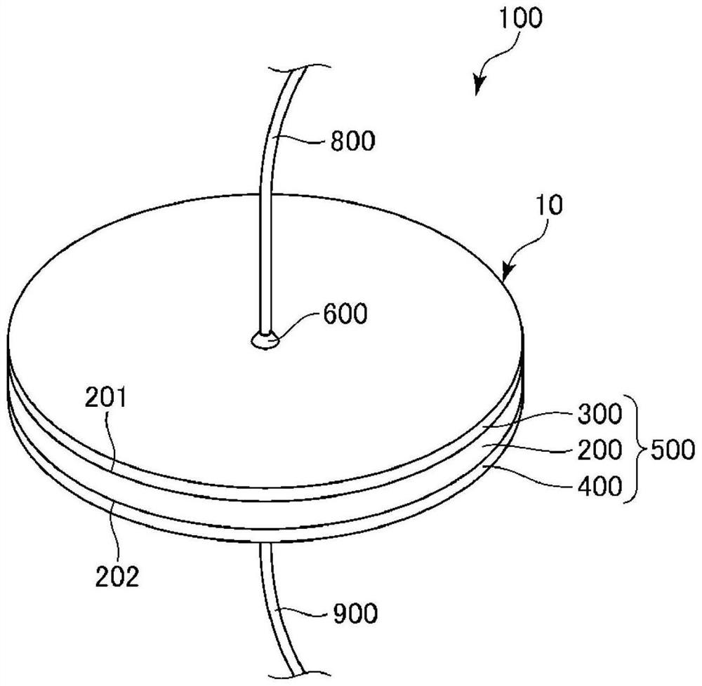
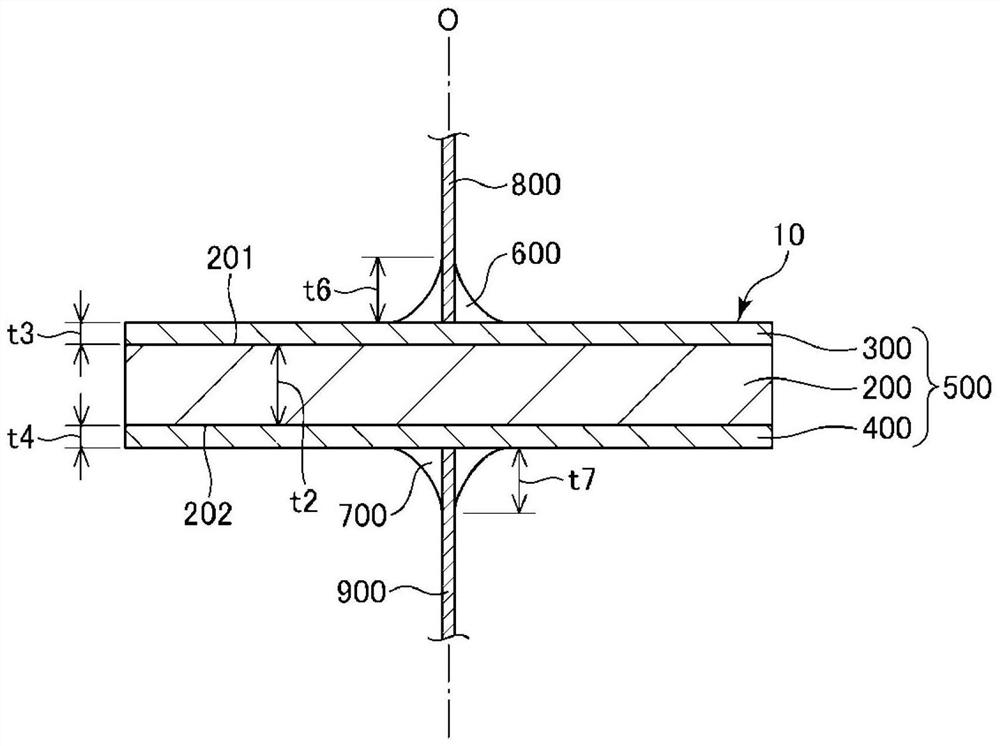
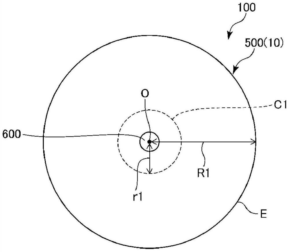
[0021] figure 1 It is a perspective view showing the piezoelectric element according to the embodiment. figure 2 Yes figure 1 Cross-sectional view of the piezoelectric element shown. image 3 Yes figure 1 Top view of the piezoelectric element shown.

[0022] 1. Piezoelectric element

[0023] figure 1 as well as figure 2 The illustrated piezoelectric element 100 includes a laminate 500 including a piezoelectric layer 200 , a first electrode layer 300 , and a second electrode layer 400 . The piezoelectric layer 200 has a first surface 201 and a second surface 202 having a front-back relationship with each other. The first electrode layer 300 is provided on the first surface 201 of the piezoelectric layer 200 . The second electrode layer 400 is provided on the second surface 202 of the piezoelectric layer 200 .

[0024] In addition, the piezoelec...


PUM


Abstract

Provided is a piezoelectric element in which the piezoelectricity is easily utilized by converting shear deformation into expansion and contraction deformation. The piezoelectric element is characterized by comprising an electric layer containing a helical chiral polymer crystal showing piezoelectricity, a first electrode layer, a second electrode layer, a first connection part provided on the side of the first electrode layer opposite to the piezoelectric layer, and a second connection part provided on the side of the second electrode layer opposite to the piezoelectric layer, when viewed in the thickness direction of the piezoelectric layer, an overlapping portion where the piezoelectric layer, the first electrode layer, and the second electrode layer overlap each other has a circular shape, and when viewed in the thickness direction of the piezoelectric layer, the first connection portion and the second connection portion overlap the center of the overlapping portion.

Description

technical field [0001] The present invention relates to piezoelectric elements. Background technique [0002] Piezoelectric polymers are used in various forms due to the unique processability of polymer materials. For example, Patent Document 1 discloses a wire-shaped piezoelectric element in which a surface of a conductive fiber formed of a conductive material is wound and covered with a piezoelectric fiber formed of a piezoelectric polymer. In such a wire-shaped piezoelectric element, a piezoelectric fiber containing a piezoelectric polymer uniaxially oriented along the fiber axis is used. In addition, Patent Document 1 discloses that the winding angle of the piezoelectric fibers with respect to the conductive fibers is an inclination direction of 15° or more and 75° or less. By setting the winding angle within such a range, shear stress can be generated in the piezoelectric fiber, and a large electrical signal can be extracted through the conductive fiber by the piezoel...

Claims


Application Information

Patent Timeline
Patent Type & Authority Applications(China)
IPC IPC(8): H01L41/193H01L41/047
CPCH10N30/872H10N30/857H10N30/875H10N30/1061
Inventor 米村贵幸加藤治郎
Owner SEIKO EPSON CORP
Why Eureka
Try Eureka