
Rotary linear mechanism for glassware forming machine

A glassware and forming machine technology, applied in the direction of blowing glass forming machine, blowing-glass forming machine, glass production, etc., can solve problems such as restricting the operation of cooling system

Pending Publication Date: 2022-07-29
VITRO SAB DE CV
View PDF7 Cites 0 Cited by
  • Summary
  • Abstract
  • Description
  • Claims
  • Application Information

AI Technical Summary

Problems solved by technology

[0018] Also, it is important to note that the rotary linear mechanism is mounted on top of the support frame, limiting the operation of the cooling system

Method used


Image

  • Rotary linear mechanism for glassware forming machine
  • Rotary linear mechanism for glassware forming machine
  • Rotary linear mechanism for glassware forming machine

Examples


Embodiment Construction

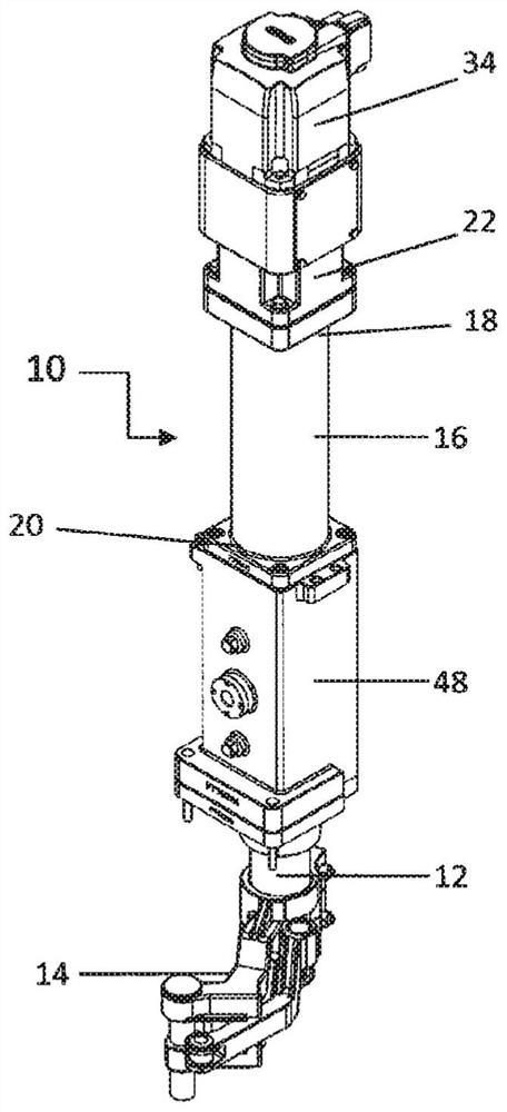
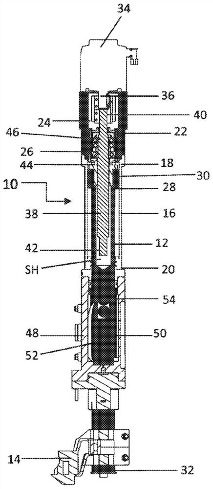
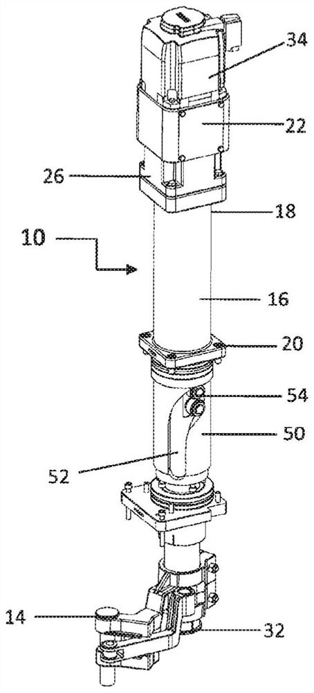
[0036] For a better understanding of the present invention, only the rotary linear mechanism 10 for the glassware forming machine will be described, without showing its coupling on the blowing head, baffle or funnel.

[0037] like figure 1As shown, a rotary linear mechanism 10 for a glassware former is primarily used to simultaneously move a shaft 12 with axial movement and an arm 14 with radial movement to the left or right. The shaft 12 is connected to the arm 14 . Arm 14 is a funnel holder arm, baffle arm or arm for the blowing head of the forming machine, which moves between an article forming position and a closed position. The shaft 12 has a hollow channel SH formed about half of the total length from the top to the shaft. It also includes a spring (not shown) located in the shaft 12 for safety purposes in the absence of electrical current, when the stored spring force is compressed, to enable the shaft to move to the up position and avoid any accident or shock.

[00...


PUM


Abstract

The invention relates to a rotary linear mechanism for a glassware forming machine, which is used for being connected with a funnel holding arm, a baffle arm, an arm for a blowing head or the like. The arms are arranged to simultaneously perform axial and radial movement of each of the arms from a first position for forming the glass article to a second position outside its forming process.

Description

technical field [0001] The present invention relates to a mechanism for use in a glassware forming machine, and more particularly to a rotary linear mechanism for a glassware forming machine that can be used to connect a funnel holding arm, a baffle arm, a arm or similar mechanism. Background technique [0002] Glassware, such as glass containers, is typically produced on glassware formers, such as these glassware formers that may include a number of similar individual forming sections, through blow-blow and pressure-blow processes, for the manufacture of wide-mouth and narrow-mouth containers , such as bottles, glasses and other glassware. These are produced on forming machines, known as "E", "F", "SF" series of pneumatic, servopneumatic and full servo technology. [0003] In the container manufacturing process by blow-blowing or blow pressing, glass in the form of a cling block is introduced into a parison or pre-mold in a parison-forming station where, according to the ...

Claims


Application Information

Patent Timeline
Patent Type & Authority Applications(China)
IPC IPC(8): C03B9/14C03B9/193
CPCC03B9/1932C03B9/165C03B9/1934C03B9/1938
Inventor V·提杰里纳拉莫斯
Owner VITRO SAB DE CV
Learn More