Multifunctional floor sweeping device

A multi-functional, installation tube technology, applied to manual sweeping machinery, machine parts, photovoltaic power generation, etc., can solve problems such as non-automatic steering, machine stuck in place, low carpet identification and obstacle avoidance, etc., to prolong the pressure time , extended time, and the effect of improving recognition accuracy

Inactive Publication Date: 2022-08-02
深圳市迅龙软件有限公司
View PDF1 Cites 0 Cited by
  • Summary
  • Abstract
  • Description
  • Claims
  • Application Information

AI Technical Summary

Problems solved by technology

[0004] When the floor sweeping machines in the prior art are in use, when encountering temporarily placed carpets, boxes and other items, they mostly perform automatic obstacle avoidance operations through laser obstacle avoidance or visual obstacle avoidance functions, but the above obstacle avoidance functions have the following disadvantages. On the one hand, laser obstacle avoidance and visual obstacle avoidance are used at the same time, and the production cost is high. On the other hand, laser obstacle avoidance is difficult to identify and avoid objects such as low carpets. Visual obstacle avoidance mostly uses cameras to identify objects. It is difficult to accurately identify at night; therefore, when the identification is inaccurate, the sweeping device will directly hit the obstacle and will not automatically turn, causing the machine to be stuck in place, which will not affect the normal operation of the sweeping device. In view of this, We propose a multifunctional sweeping device

Method used


Image

  • Multifunctional floor sweeping device
  • Multifunctional floor sweeping device
  • Multifunctional floor sweeping device

Examples


Embodiment Construction

[0036] The following description serves to disclose the invention to enable those skilled in the art to practice the invention. The preferred embodiments described below are given by way of example only, and other obvious modifications will occur to those skilled in the art.

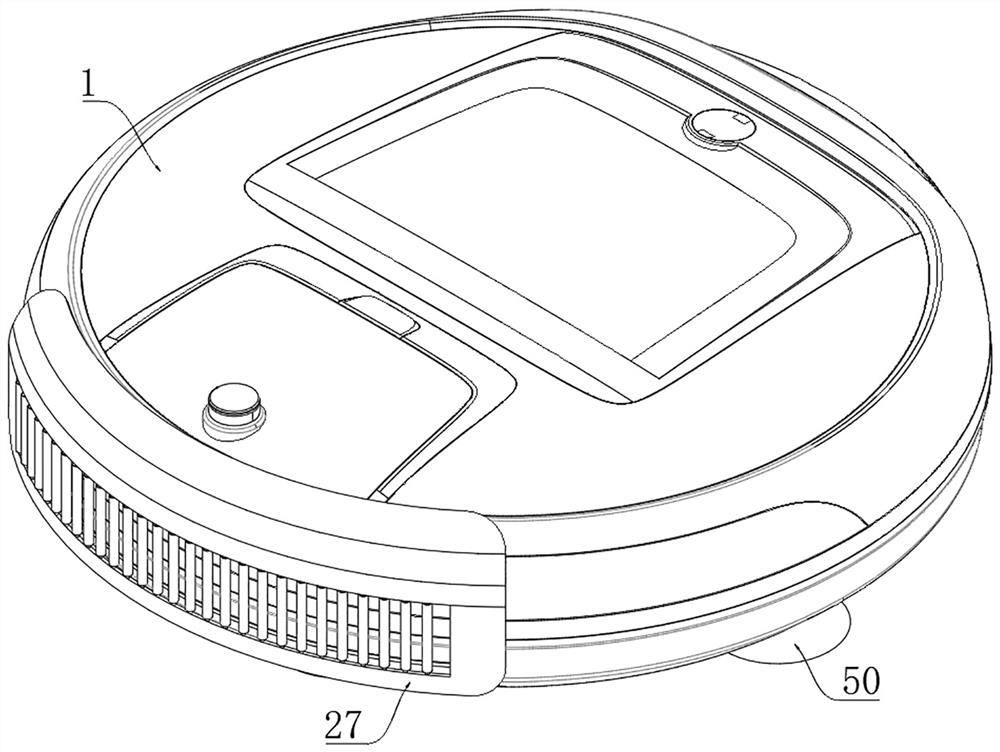
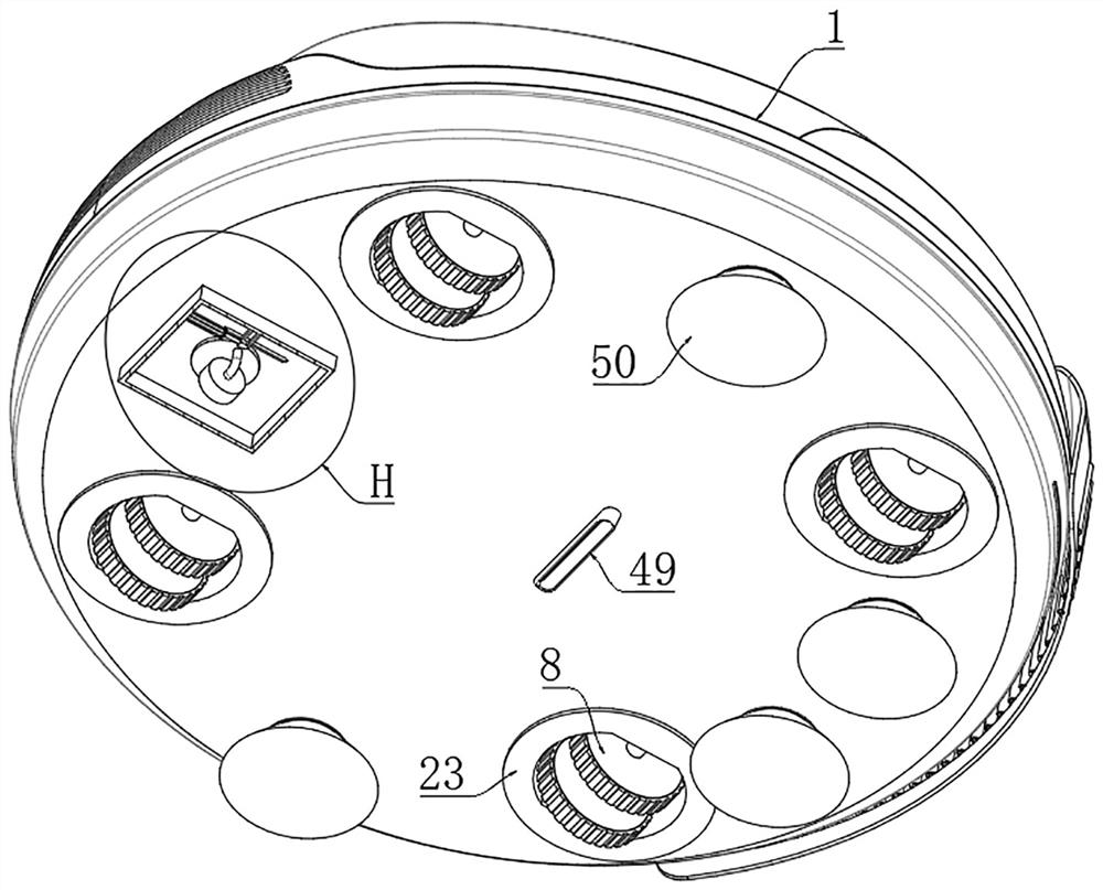
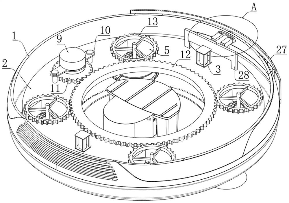
[0037] like Figure 1 to Figure 15 The shown multifunctional sweeping device includes a casing 1, a cleaning mechanism for cleaning garbage is arranged on the bottom surface of the casing 1, a dust suction mechanism for absorbing dust is arranged in the middle of the casing 1, and the interior of the casing 1 is placed. There is a support ring 2, a plurality of electric cylinders 3 are fixed on the top surface of the support ring 2, and the piston rods of the plurality of electric cylinders 3 all penetrate the support ring 2 and extend out and then be fixed on the inner bottom surface of the housing 1; the support ring 2 The top surface of the casing 1 is provided with four through holes 4 in a circular...


PUM


Abstract

The invention relates to the technical field of transmission devices, in particular to a multifunctional floor sweeping device which comprises a shell, a sweeping mechanism used for sweeping garbage is arranged on the bottom face of the shell, a dust suction mechanism used for sucking dust is arranged in the middle of the shell, and a supporting ring is placed in the shell. A plurality of electric cylinders are fixed to the top face of the supporting ring, and piston rods of the multiple electric cylinders penetrate through the supporting ring, extend out and then are fixed to the inner bottom face of the shell. Four through holes are formed in the top face of the supporting ring in a circumferential array mode, and rotating cylinders are rotationally connected to the interiors of the four through holes correspondingly. Through cooperation with an obstacle avoidance system or a laser obstacle avoidance system on an existing sweeping machine, the robot automatically crosses or bypasses an obstacle after colliding with an object, and the problems that after an existing obstacle avoidance function is inaccurate in recognition, the sweeping machine directly collides with the object and does not automatically steer, so that the robot is stuck in situ, and the robot cannot be damaged are solved. And the recognition accuracy of the existing obstacle avoidance system can be improved.

Description

technical field [0001] The invention relates to the field of transmission devices, in particular to a multifunctional sweeping device. Background technique [0002] As an automatic cleaning intelligent device, the sweeping robot plays an important role in people's daily life and greatly improves people's quality of life. [0003] Some invention patents related to sweeping devices are disclosed in the prior art. The Chinese patent with the application number of 202110310461.9 discloses a sweeping robot, wherein the sweeping robot includes a sweeper body, a mopping assembly and a first driving device, wherein the mopping The floor assembly is movably switchable between the first storage position and the mopping position and is installed on the main body of the sweeper; the first driving device is installed in the main body of the sweeper and is drivingly connected with the mopping assembly for use in the sweeper body. When the mopping assembly is driven to be in the first sto...

Claims


Application Information

Patent Timeline
Patent Type & Authority Applications(China)
IPC IPC(8): A47L11/24A47L11/40
CPCA47L11/24A47L11/4002A47L11/4008A47L11/4011A47L2201/04A47L2201/00Y02E10/50
Inventor 赵一帆
Owner 深圳市迅龙软件有限公司
Why Eureka
Try Eureka