Drying mechanism of floor brush and cleaning equipment thereof

A technology for cleaning equipment and drying, applied in dryers, drying gas layout, lighting and heating equipment, etc., can solve problems such as rising costs, erroneous startup of drying devices, and major safety risks, saving design, development and manufacturing costs. , The effect of reducing the probability of false start and shortening the drying time

Pending Publication Date: 2022-08-02
ZHEJIANG HUAGUANG ELECTRIC APPLIANCE GRP
View PDF1 Cites 2 Cited by
  • Summary
  • Abstract
  • Description
  • Claims
  • Application Information

AI Technical Summary

Problems solved by technology

[0006] After the applicant tested and used the above-mentioned patented product, it was found that there were certain deficiencies in it, for example: 1. The base used for cleaning equipment only plays a supporting and charging role, so its structure is relatively simple, and the drying device is integrated in the When it is in the base, it will greatly increase the structural complexity of the base. The shell of the base needs to be replanned and designed, and the production mold will be re-opened, so the cost will increase greatly; 2. In order to meet the structure of the base, the air duct parts need to extend from the rear of the base To the front end, the air duct is too long, the same fan power after passing through the long air duct, the air output rate is small, and the air drying effect on the roller brush is poor, so it will take longer drying time; The devices are concentrated in the base, and the base is usually placed on the ground, which is easy to be touched by children and cause the drying device to be activated by mistake, so there is a greater safety risk

Method used


Image

  • Drying mechanism of floor brush and cleaning equipment thereof
  • Drying mechanism of floor brush and cleaning equipment thereof
  • Drying mechanism of floor brush and cleaning equipment thereof

Examples


Embodiment 2

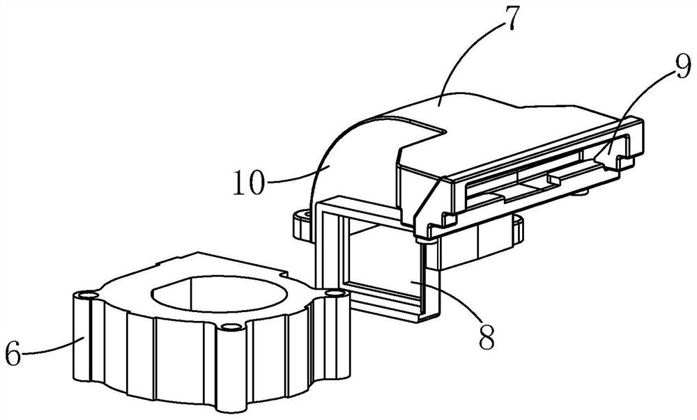
[0058] In order to realize the diversified functions of the base 2 , in particular, a charging function can be provided to the host part, so as to increase the battery life. The structural scheme adopted in this embodiment is: refer to Figure 4 to Figure 5 , the base 2 includes a tray 11 and a support frame 12 protruding from the tray 11, the support frame 12 is provided with a first charging assembly 13, and the first charging assembly 13 can be connected to an external power source ; The host shell 1 is provided with a battery assembly 32 and a second charging assembly 14, and the second charging assembly 14 is connected to the battery assembly 32; when the host shell 1 is placed on the base 2 , the first charging assembly 13 and the second charging assembly 14 are electrically connected to charge the battery assembly 32 in the host housing 1 .

[0059] The structure of the above-mentioned charging portion is substantially the same as the charging structure in the prior ar...

Embodiment 3

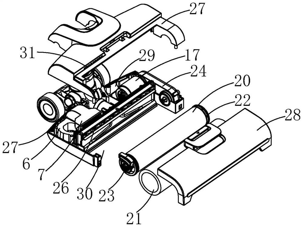
[0061] Since the base 2 is provided with the first charging assembly 13, when the base 2 is powered on and the host housing 1 is not placed, there is a certain risk if the first charging assembly 13 is exposed to the outside, and the safety standard cannot be met. At the same time, the first charging assembly 13 itself is also easily damaged by external impact.

[0062] Therefore, on the basis of the second embodiment, this embodiment adds a protection structure, which is as follows: refer to Figure 4 , the support frame 12 is also provided with a baffle assembly 15, the baffle assembly 15 has an open position state and a blocking position state. The specific situation in use is: when the host housing 1 is placed on the base 2, the baffle assembly 15 is switched to the open position to form a docking opening 16, so as to realize the first charging assembly 13 and the second charging assembly 15. The docking of the charging assembly 14 ; when the host housing 1 leaves the bas...

Embodiment 4

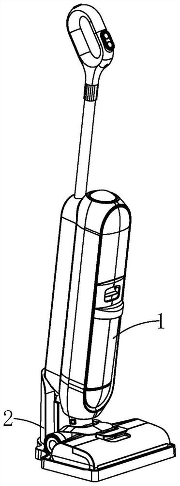
[0064] refer to Figure 1 to Figure 11 , the present invention also provides a cleaning device, including the drying mechanism of the floor brush mentioned above; also includes a driving mechanism, which acts on the roller brush assembly 3 so that the roller brush assembly 3 can be relative to the main casing. The body 1 rotates; when in use, the drive mechanism is turned on, so that the roller brush assembly 3 rotates continuously to clean the ground more effectively. At the same time, when the air-drying mechanism is running, the roller brush assembly 3 can also be operated by the driving mechanism at the same time, so as to further improve the overall drying effect of the roller brush assembly 3 .

[0065] In a conventional product, the rolling brush assembly 3 is in the front, and the driving mechanism is behind, and the driving mechanism drives the rolling brush assembly 3 to rotate through a transmission mechanism on one side. However, it has certain defects. For exampl...


PUM


Abstract

The invention discloses a floor brush drying mechanism and cleaning equipment thereof. The floor brush drying mechanism comprises a main machine shell; the base is used for supporting and placing the host shell; the rolling brush assembly is assembled in the main machine shell, and the main machine shell can drive the rolling brush assembly to move together under the action of external force; the air drying mechanism is arranged in the main machine shell; the starting mechanism comprises a circuit control system arranged in the base or the main machine shell, an air drying circuit triggering end arranged in the base and an air drying circuit receiving end arranged in the main machine shell, and when the air drying circuit triggering end is connected with the air drying circuit receiving end, the circuit control system controls the air drying mechanism to be started; and the air is blown to the rolling brush assembly. The air drying mechanism is integrated in the floor brush shell, so that the structure of the base does not need to be changed, meanwhile, the overall shape of the host does not need to be greatly changed, and the design, development and manufacturing cost is greatly saved.

Description

technical field [0001] The invention relates to the technical field of floor brushes in cleaning equipment, in particular to a drying mechanism for floor brushes and cleaning equipment thereof. Background technique [0002] With the development of the economy and the progress of the society, people have higher and higher requirements for the quality of life. Therefore, some smart appliances that can free people's hands have emerged, and the floor washing machine used for indoor floor cleaning has gradually entered people's lives. The floor scrubber is a cleaning machine suitable for cleaning hard floors while absorbing sewage and taking the sewage away from the site. It has the advantages of environmental protection, energy saving and high efficiency. The scrubbers are semi-automatic scrubbers, fully automatic scrubbers, hand push scrubbers, and ride-on scrubbers. [0003] With the continuous improvement of cleaning requirements and the development of mechanization process,...

Claims


Application Information

Patent Timeline
Patent Type & Authority Applications(China)
IPC IPC(8): A47L11/30A47L11/40F26B21/00
CPCA47L11/302A47L11/40A47L11/4011A47L11/4041F26B21/004Y02B40/00
Inventor 贺艳城徐敏霞
Owner ZHEJIANG HUAGUANG ELECTRIC APPLIANCE GRP
Why Eureka
Try Eureka