Driving control system and method for independent electric drive loading machine additionally provided with clutch

A drive control and loader technology, applied in the field of shoveling construction machinery, can solve problems such as waste of energy, maintenance difficulties, and energy waste, and achieve the effects of reducing parasitic power, improving use efficiency, and reducing manufacturing costs

Pending Publication Date: 2022-08-02
HUAIAN COLLEGE OF INFORMATION TECH
View PDF4 Cites 1 Cited by
  • Summary
  • Abstract
  • Description
  • Claims
  • Application Information

AI Technical Summary

Problems solved by technology

[0004] The engine consumes a lot of fuel, wastes energy and pollutes the environment
The transmission efficiency of the hydraulic torque converter is low, and the average efficiency is only about 30% during general work; the power shift transmission used for loaders is a multi-speed transmission, generally three forwards and three backwards or four forwards four One gear; transmission gear shifting adopts hydraulic manual operation, complex structure, high manufacturing cost and difficult maintenance
During the driving process of the four-wheel drive loader, due to the large change in the load on the front and rear axles, the radius of the tires on the front and rear axles also changes greatly, so the parasitic work produced by the loader due to the same angular velocity and different linear velocity of the front and rear wheels during the working process has reached More than 20% of the driving power, resulting in a huge waste of energy
[0005] In invention patents CN201911216703.7, CN201510559655.7 and utility model patents CN201922126881.2 and CN201520682565.2, the front and rear axle independent drive loader structure is proposed, especially CN201510559655.7 also does the driving torque distribution of front and rear axle independent drive loaders Corresponding research has been carried out, but only the efficiency of the motor and the situation of motor slippage have been discussed, and the standard operating conditions of the loader and the characteristics of the front and rear axle motors have not been considered realistically. There will be certain differences in actual production. limitations

Method used


Image

  • Driving control system and method for independent electric drive loading machine additionally provided with clutch
  • Driving control system and method for independent electric drive loading machine additionally provided with clutch
  • Driving control system and method for independent electric drive loading machine additionally provided with clutch

Examples


Embodiment Construction

[0079] The present invention will be described in detail below in conjunction with the accompanying drawings and the embodiments, but those skilled in the art should know that the following embodiments are not the only limitations to the technical solutions of the present invention, and any work done under the spirit of the technical solutions of the present invention Equivalent transformation or modification shall be regarded as belonging to the protection scope of the present invention.

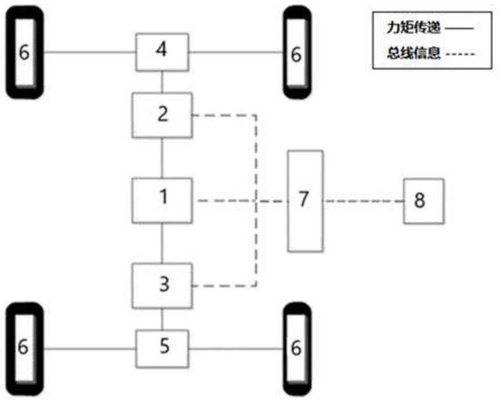
[0080] The invention provides a drive control system of a loader. The system is to install motors on the front and rear axles of the loader to drive the front and rear axles independently, and install a main reducer on the front and rear axles respectively, and install a wheel side reducer on the wheels. A new configuration of adding a clutch device between the two motors to increase the transmission ratio to meet the driving force requirements of the loader under shovelling conditions.

[...


PUM


Abstract

The invention provides a drive control system and method for an independent electric drive loading machine with a clutch, the drive control system of the loading machine is additionally provided with two main speed reducers through a front axle and a rear axle, is additionally provided with two motors through the front axle and the rear axle, is additionally provided with a clutch between the two motors, and is additionally provided with a hub speed reducer on each wheel. According to the invention, different values are given to the required torques of the two motors through the separation and combination of the clutch and the two motors under different working conditions of the loader, so that the two motors work with different driving forces, the four-wheel drive working requirements of the loader are met, the parasitic power is reduced to the greatest extent, and the use efficiency of the motors and the reasonable distribution of resources are improved.

Description

technical field [0001] The invention relates to the technical field of scraper construction machinery, in particular to a drive control system and method for a loader with an energy-saving independent electric drive and a clutch. Background technique [0002] Loaders are used for loading, unloading, pushing and construction operations of bulk materials such as soil, gravel, coal, etc. They are widely used in various construction sites. At present, the driving control system of wheel loader generally adopts the internal combustion engine as the power, and the transmission device is the hydraulic transmission, which is mainly composed of the engine, the torque converter, the power shift transmission, the transmission shaft, and the drive axle. The power transmission system of this method is mature in technology, and the engine is generally dominated by diesel engines. [0003] But its disadvantages are: [0004] The engine consumes a lot of fuel, wastes energy and pollutes t...

Claims


Application Information

Patent Timeline
Patent Type & Authority Applications(China)
IPC IPC(8): B60L15/20B60L15/32
CPCB60L15/20B60L15/32B60L2220/42B60L2240/421B60L2240/423B60L2240/461Y02T10/72
Inventor 韩云武鲍常山贾金山孙彩凤陈纪龙付全硕蒋满
Owner HUAIAN COLLEGE OF INFORMATION TECH
Why Eureka
Try Eureka