
Optical filter switcher, camera module and terminal equipment

An optical filter and switcher technology, which is applied to instruments, optics, optical components, etc., can solve the problems of unfavorable miniaturization design of filter switchers, large space occupied by filter switchers, and large driving stroke, etc. Realize the effect of miniaturized design, small overall volume, and reduced driving stroke

Active Publication Date: 2022-08-02
NANCHANG OFILM HUAGUANG TECH CO LTD +1
View PDF3 Cites 0 Cited by
  • Summary
  • Abstract
  • Description
  • Claims
  • Application Information

AI Technical Summary

Problems solved by technology

However, with this electromagnetic drive conversion method, it is necessary to use the coil to cooperate with the magnetic parts to generate a large magnetic force to realize the switching of the optical filter, and the driving stroke is large, so a large space needs to be reserved, resulting in the occupation of the optical filter switch. The space is large, which is not conducive to the miniaturization design of the filter switcher

Method used


Image

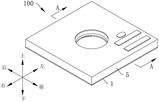
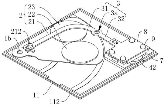
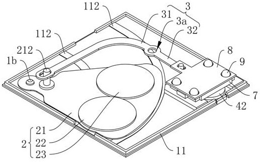
  • Optical filter switcher, camera module and terminal equipment
  • Optical filter switcher, camera module and terminal equipment
  • Optical filter switcher, camera module and terminal equipment

Examples


Embodiment Construction

[0047] The technical solutions in the embodiments of the present invention will be clearly and completely described below with reference to the accompanying drawings in the embodiments of the present invention. Obviously, the described embodiments are only a part of the embodiments of the present invention, but not all of the embodiments. Based on the embodiments of the present invention, all other embodiments obtained by those of ordinary skill in the art without creative efforts shall fall within the protection scope of the present invention.

[0048] In the present invention, the terms "upper", "lower", "left", "right", "front", "rear", "top", "bottom", "inner", "outer", "middle", The orientation or positional relationship indicated by "vertical", "horizontal", "horizontal", "longitudinal", etc. is based on the orientation or positional relationship shown in the drawings. These terms are primarily used to better describe the invention and its embodiments, and are not intend...


PUM


Abstract

The invention discloses an optical filter switcher, a camera module and a terminal device, the optical filter switcher comprises a base, an optical filter assembly, a swing arm rod and an actuating assembly, the optical filter assembly comprises an optical filter support, a first optical filter and a second optical filter, a second rotating part of the optical filter support is rotatably connected with a first rotating part of the base, and the first rotating part of the base is rotatably connected with a second rotating part of the swing arm rod. The first optical filter and the second optical filter are arranged on the optical filter support, the connecting part of the optical filter support is closer to the second rotating part than the first optical filter and the second optical filter, one end of the swing arm rod is connected with the connecting part, the actuating assembly is connected with one end of the swing arm rod, and the actuating assembly drives the swing arm rod to move so as to drive the optical filter support to rotate around the first rotating part. Therefore, the optical filter assembly is switched between the state that the first optical filter is arranged corresponding to the first light through hole and the state that the second optical filter is arranged corresponding to the first light through hole. By adopting the scheme, the overall size of the optical filter switcher is smaller, and the miniaturization design is realized.

Description

technical field [0001] The present invention relates to the technical field of camera devices, and in particular, to a filter switcher, a camera module and terminal equipment. Background technique [0002] A filter switcher (i.e. IR-CUT) is a filter switching device that switches the filter to an infrared filter during the day to filter out infrared rays to avoid image distortion, and switches to an infrared filter at night. Full spectrum filter to increase the imaging brightness of the night camera module. [0003] In the related art, the filter switcher mainly achieves the purpose of switching the filter by using the magnetic force generated by the coil and the magnetic component. However, with this electromagnetic drive conversion method, it is necessary to use the coil to cooperate with the magnetic component to generate a large magnetic force to realize the switching of the filter, and the driving stroke is large, and a large space needs to be reserved, resulting in th...

Claims


Application Information

Patent Timeline
Patent Type & Authority Applications(China)
IPC IPC(8): G03B17/14G02B7/00G03B30/00
CPCG03B17/14G02B7/006G03B30/00
Inventor 赵伟李巍
Owner NANCHANG OFILM HUAGUANG TECH CO LTD
Learn More