Portable MC4 photovoltaic connector separating device

A photovoltaic connector, portable technology, applied in the parts of the connection device, connection, coupling device, etc., can solve the problems of heat generation, affecting service life, and being easily affected by dust, so as to prolong the service life and improve the installation stability , to achieve the effect of cooling

Pending Publication Date: 2022-08-02
中节能莲花太阳能科技有限公司
View PDF0 Cites 0 Cited by
  • Summary
  • Abstract
  • Description
  • Claims
  • Application Information

AI Technical Summary

Problems solved by technology

[0004] In view of the above situation, in order to overcome the defects of the prior art, the present invention provides a portable MC4 photovoltaic connector separation device, which effectively solves the problem that the MC4 photovoltaic connector in the above background technology is easily affected by dust due to its exposure to the external environment. , At the same time, heat will be generated during work, which will affect its service life

Method used


Image

  • Portable MC4 photovoltaic connector separating device
  • Portable MC4 photovoltaic connector separating device
  • Portable MC4 photovoltaic connector separating device

Examples


Embodiment 1

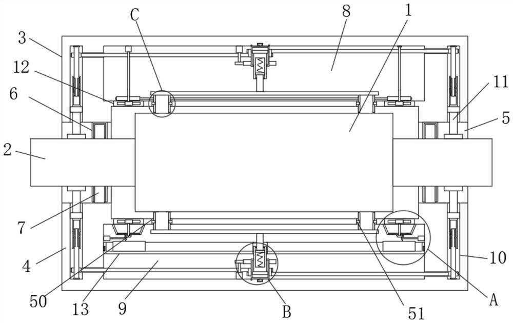
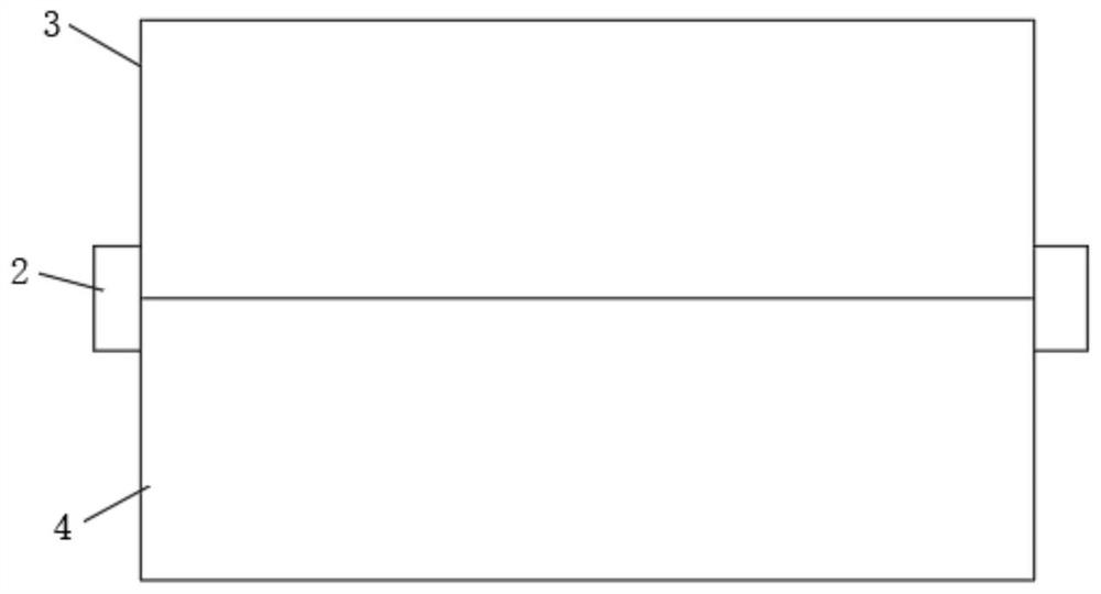
[0034] Example one, by Figure 1 to Figure 8Given, the present invention includes a MC4 connector body 1, both ends of the MC4 connector body 1 are provided with connecting ends 2, the outer cover of the MC4 connector body 1 is provided with a protective sleeve 3 and a protective sleeve 2 4, and the protective sleeve 1 3 is located above the protective sleeve 2 4 , both sides of the protective sleeve 1 3 and the protective sleeve 2 4 are provided with a first through port 5 , the connecting end 2 runs through the interior of the first through port 5 , and the first through port 5 is The inner top end is equipped with a collar 6 , the inner bottom end of the first through port 5 is provided with an insertion rod 7 which is inserted into the inner part of the collar 6 , the inner part of the protective sleeve 3 is provided with an accommodation groove 1 8 , and the inner part of the protective sleeve 2 4 is provided. An accommodation groove 2 9 is opened inside, and a threaded g...

Embodiment 2

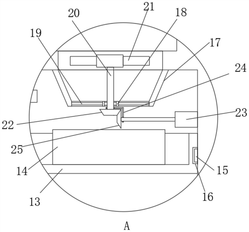
[0036] Embodiment 2, on the basis of Embodiment 1, by figure 1 and image 3 Given, the inner top of the receiving groove 9 is installed with a shroud 17 located outside the two second ports 12, and a fixing block 18 is provided in the middle of the bottom end of the shroud 17. The fixing block 18 and the shroud 17 The inner walls of the ducts are connected by fixed rods 19 arranged at equal distances. The shroud 17 is located directly above the collection box 14, and the cross section of the shroud 17 is an inverted trapezoidal structure. The suction fan 21, the first bevel gear 22, the motor one 23, the connecting seat 24 and the second bevel gear 25, the fixed block 18 is rotatably installed with a rotating shaft one 20, and the top of the rotating shaft one 20 is provided with a second port 12 The inner suction fan 21, the bottom end of the rotating shaft 1 20 is provided with a bevel gear 1 22 located under the fixed block 18, the inner wall of the receiving groove 2 9 is...

Embodiment 3

[0038] Embodiment 3, on the basis of Embodiment 1, by figure 1 and Figure 4 Given, the blowing group includes a second motor 26, a second rotating shaft 27, a blowing fan 28, a single pulley 1 29 and a connecting belt 1 30, the inner top of the receiving groove 18 is installed with a second motor 26 and a second rotating shaft 27, and the second rotating shaft 27 is located on one side of the second motor 26. The output shaft of the second motor 26 and the second rotating shaft 27 are provided with a single pulley 29 and a blowing fan 28. The blowing fan 28 is located inside the second port 12, and the blowing fan 28 is located at Below the single pulley one 29, the two single pulley one 29 are connected by the connecting belt one 30;

[0039] By starting the second motor 26, the second motor 26 drives one of the single pulleys 29 and one of the blowing fans 28 to rotate, and the other single pulley 29 is rotated through the connection relationship of the connecting belt 1 3...


PUM


Abstract

The invention relates to the technical field of MC4 photovoltaic connectors, and discloses a portable MC4 photovoltaic connector separating device, which solves the problems that the MC4 photovoltaic connector is easily influenced by dust when exposed in the external environment, and the service life of the MC4 photovoltaic connector is influenced by heat generated during working, and comprises an MC connector body, the two ends of the MC connector body are provided with connecting ends, the MC connector body is sleeved with a first protective sleeve and a second protective sleeve, the first protective sleeve is located above the second protective sleeve, the two sides of the first protective sleeve and the two sides of the second protective sleeve are each provided with a first through opening, the connecting ends penetrate through the first through openings, and lantern rings are installed at the inner top ends of the first through openings. Through the design of the distance adjusting mechanism, the first clamping rod and the clamping mechanism, clamping of the connecting end and the MC connector body is achieved conveniently, then the installation stability of the MC connector body is improved, and protection of the MC connector body is effectively achieved.

Description

technical field [0001] The invention belongs to the technical field of MC4 photovoltaic connectors, in particular to a portable MC4 photovoltaic connector separation device. Background technique [0002] With the country's strong support for the photovoltaic industry, the development of photovoltaic products has gradually diversified, and has entered all aspects of life. At present, the photovoltaic DC wiring method mainly uses MC4 male and female connectors to connect. The risk of arcing, short circuit, and even fire in severe cases, the existing MC4 photovoltaic connector is equipped with a separate device to protect it. [0003] However, the MC4 photovoltaic connector needs to detach the separate device from it during operation, which will expose it to the external environment and make it vulnerable to dust. At the same time, it will generate heat during operation, which will affect its service life. SUMMARY OF THE INVENTION [0004] In view of the above situation, in ...

Claims


Application Information

Patent Timeline
Patent Type & Authority Applications(China)
IPC IPC(8): H01R13/639H01R13/629H05K7/20B08B5/04
CPCH01R13/639H01R13/629H05K7/20136B08B5/04Y02E10/50
Inventor 谢包胜
Owner 中节能莲花太阳能科技有限公司
Why Eureka
Try Eureka