Soil throwing type ridging device

A soil throwing board and soil crushing technology, which is applied in planting methods, agricultural machinery and tools, and digging/covering ditches, etc., can solve the problems of inability to meet the needs of ridging, limited height of ridging, and easy overload of the throwing turntable. Work and other issues, to achieve the effect of reducing manual workload, high ridge efficiency, safe use and good stability

Pending Publication Date: 2022-08-05
SOUTH CHINA AGRI UNIV
View PDF10 Cites 1 Cited by
  • Summary
  • Abstract
  • Description
  • Claims
  • Application Information

AI Technical Summary

Problems solved by technology

The earth-throwing fire extinguisher in this scheme is used for throwing soil and ridges. When the engine is started, the power is transmitted from the power output shaft to the cutter shaft and the gearbox through the transfer box, and then transmitted to the turntable for throwing soil after being shifted by the gearbox. The shaft rotates to crush the soil and raise the crushed soil to the soil throwing turntable, and the soil throwing turntable finally throws the crushed soil to the banana tree. However, in this scheme, the soil throwing turntable is easily overloaded and does not work, and the height of the ridging is limited, which cannot meet the requirements. Ridging requirements under the "ultra-wide and narrow row" banana planting mode

Method used


Image

  • Soil throwing type ridging device
  • Soil throwing type ridging device
  • Soil throwing type ridging device

Examples


Embodiment 1

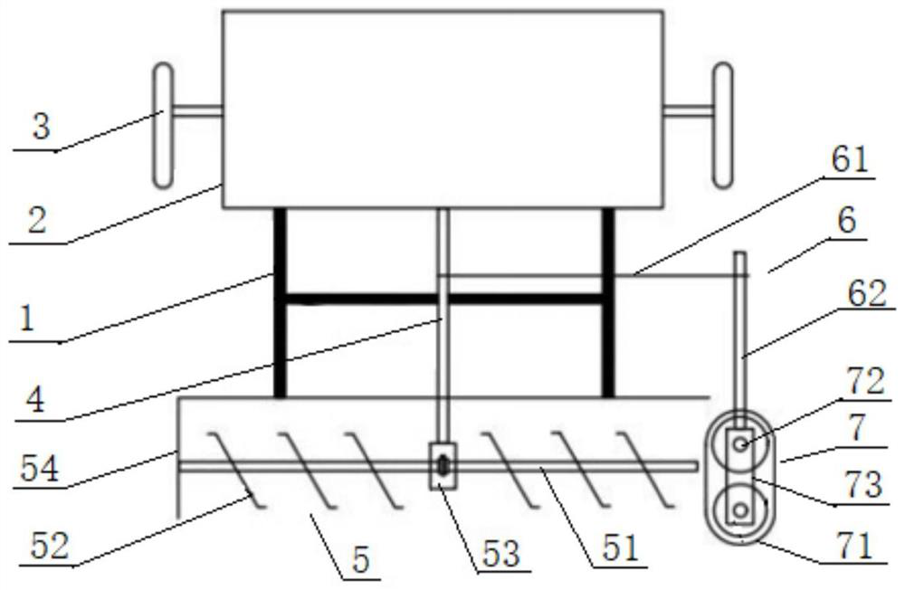
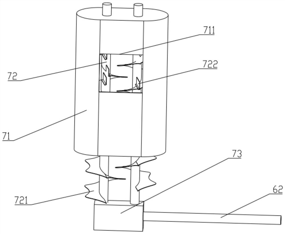
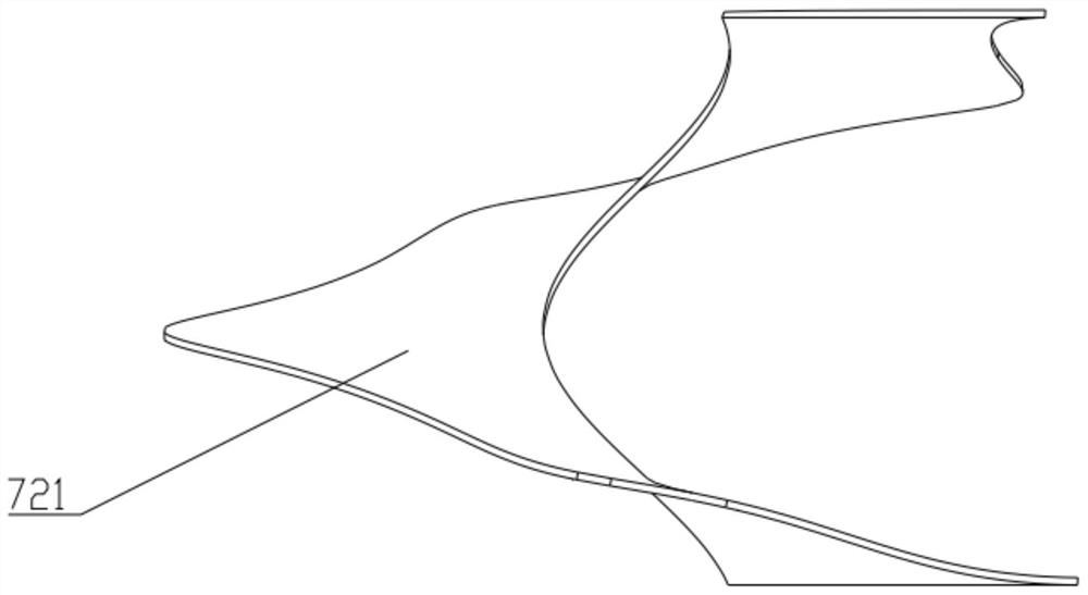
[0028] A soil throwing type ridge device, such as figure 1 , figure 2 As shown, it includes a frame 1, a power assembly 2, a soil breaking mechanism 5 and a soil throwing mechanism 7. The power assembly 2 is connected to the front of the frame 1, and the soil breaking mechanism 5 is connected to the rear of the frame 1. The soil mechanism 7 is located at the end of the soil crushing mechanism 5, and the soil crushing mechanism 5 and the soil throwing mechanism 7 are respectively connected with the output end of the power assembly 2; the output end of the power assembly 2 is connected with the traveling mechanism 3 for driving the ridge device The soil throwing mechanism 7 includes a fixed cover 71 and a number of screw augers 72. The fixed cover 71 is located at the end of the soil crushing mechanism 5, and the soil crushing mechanism 5 can transport the crushed soil to the bottom of the fixed cover 71. Several screw augers 72 are rotated and installed on Inside the fixed co...

Embodiment 2

[0035] This embodiment is similar to the first embodiment, the difference is that, as figure 1 As shown, the soil crushing mechanism 5 includes a cutter shaft 51 and a plurality of blades 52. The output shaft 4 is connected to the cutter shaft 51 through a first turbine box 53. A plurality of blades 52 are respectively fixed on the cutter shaft 51, and a plurality of blades 52 are in a spiral structure. Distribution, the fixed cover 71 is located on the side of one end of the cutter shaft 51 . During implementation, the power assembly 2 drives the output shaft 4 to rotate, and the first turbine box 53 makes the cutter shaft 51 rotate at a high speed. Broken, and because the blades 52 are distributed in a spiral structure, during the rotation of the blade shaft 51 , the blades 52 transport the crushed soil to one end of the blade shaft 51 and finally to the bottom of the fixed cover 71 .

[0036] like figure 1 As shown, a protective shell 54 is also included, and the frame 1 ...

Embodiment 3

[0038] This embodiment is similar to the second embodiment, the difference is that, as figure 1 As shown, several screw augers 72 are drivingly connected with the output shaft 4 through the transmission assembly 6 .

[0039] like figure 1 As shown, the transmission assembly 6 includes a transmission shaft 62, a belt 61, a first pulley and a second pulley connected by the belt 61. The first pulley and the second pulley are respectively coaxially connected with the output shaft 4 and the transmission shaft 62. The transmission shaft 62 Arranged in parallel with the output shaft 4 , the transmission shaft 62 is rotatably connected with the fixed cover 71 , and the transmission shaft 62 is connected with a plurality of screw augers 72 through a second turbine box 73 . During implementation, the power assembly 2 drives the output shaft 4 and the first pulley on it to rotate, drives the second pulley and the transmission shaft 62 to rotate through the belt 61, and drives a number o...


PUM


Abstract

The invention relates to the technical field of agricultural mechanical equipment, in particular to a soil throwing type ridging device which comprises a rack, a power assembly, a soil crushing mechanism and a soil throwing mechanism, the power assembly is connected to the front portion of the rack, the soil crushing mechanism is connected to the rear portion of the rack, and the soil crushing mechanism and the soil throwing mechanism are connected with the output end of the power assembly; the output end of the power assembly is connected with a walking mechanism, the soil throwing mechanism comprises a fixing cover and a plurality of spiral augers, the fixing cover is located at the tail end of the soil crushing mechanism, the soil crushing mechanism can convey crushed soil to the bottom of the fixing cover, the spiral augers are rotationally installed in the fixing cover, and a window is formed in the outer side of the top of the fixing cover. The output end of the power assembly is connected with the spiral packing auger so as to drive the spiral packing auger to convey crushed soil to the window to be thrown out. According to the device, soil in furrows can be stably, continuously and accurately scattered to the surface of banana tree disks, ridges with certain height and width are formed, and the ridging requirement in an ultra-wide and narrow-row banana planting mode is met.

Description

technical field [0001] The present invention relates to the technical field of agricultural machinery and equipment, and more particularly, to a soil throwing type ridge device. Background technique [0002] Banana is a fruit of the Musaceae plant in subtropical regions. It is rich in nutrients such as protein, vitamin A, and dietary fiber. It has miraculous effects on protecting gastric mucosa and lowering blood pressure. It is deeply loved by consumers. The annual consumption of bananas in my country is increasing year by year. Ridging is an important step before planting banana trees. It can adjust soil moisture and improve soil aeration. It is one of the key steps in the growth of banana trees and one of the key links in improving banana fruit quality. [0003] At present, the new planting model of "super wide and narrow row" is being tried out in banana orchards in South China. In the new model, the height of the ridge is about 60cm, the width of the ridge is 5-6m, and ...

Claims


Application Information

Patent Timeline
IPC IPC(8): A01C5/06A01B49/02
CPCA01C5/064A01B49/022A01B49/027
Inventor 高锐涛高宇李君孙志全曹璨闫华超郭亮李岚潇资乐侯康林达伟
Owner SOUTH CHINA AGRI UNIV
Why Eureka
Try Eureka