
Compression device for bedridden patient after radial artery blood gas collection

A radial artery and blood gas technology, applied in the field of medical equipment, can solve the problems of reducing the work efficiency of medical staff and taking a long time, and achieve the effects of easy clamping, convenient use, and improved work efficiency

Pending Publication Date: 2022-08-05
滨州医学院烟台附属医院
View PDF0 Cites 0 Cited by
  • Summary
  • Abstract
  • Description
  • Claims
  • Application Information

AI Technical Summary

Problems solved by technology

[0004] The purpose of the present invention is to solve the problem in the prior art that most of the bleeding is stopped by medical personnel pressing the hemostatic cotton pad after radial artery blood gas collection, which takes a long time. In order to overcome the shortcomings of the work efficiency of medical staff, a compression device after radial artery blood gas collection for bedridden patients is proposed

Method used


Image

  • Compression device for bedridden patient after radial artery blood gas collection
  • Compression device for bedridden patient after radial artery blood gas collection
  • Compression device for bedridden patient after radial artery blood gas collection

Examples


Embodiment 1

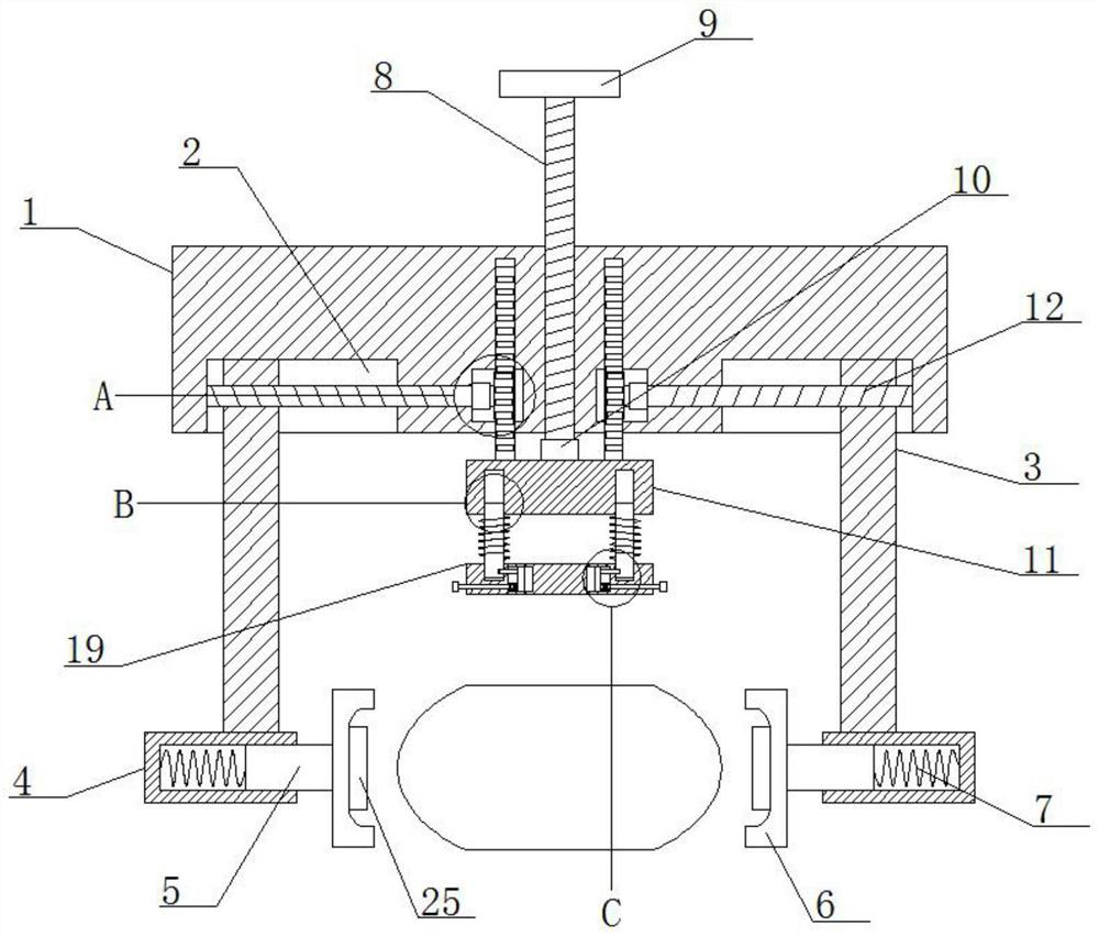
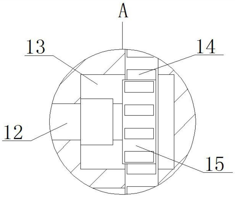
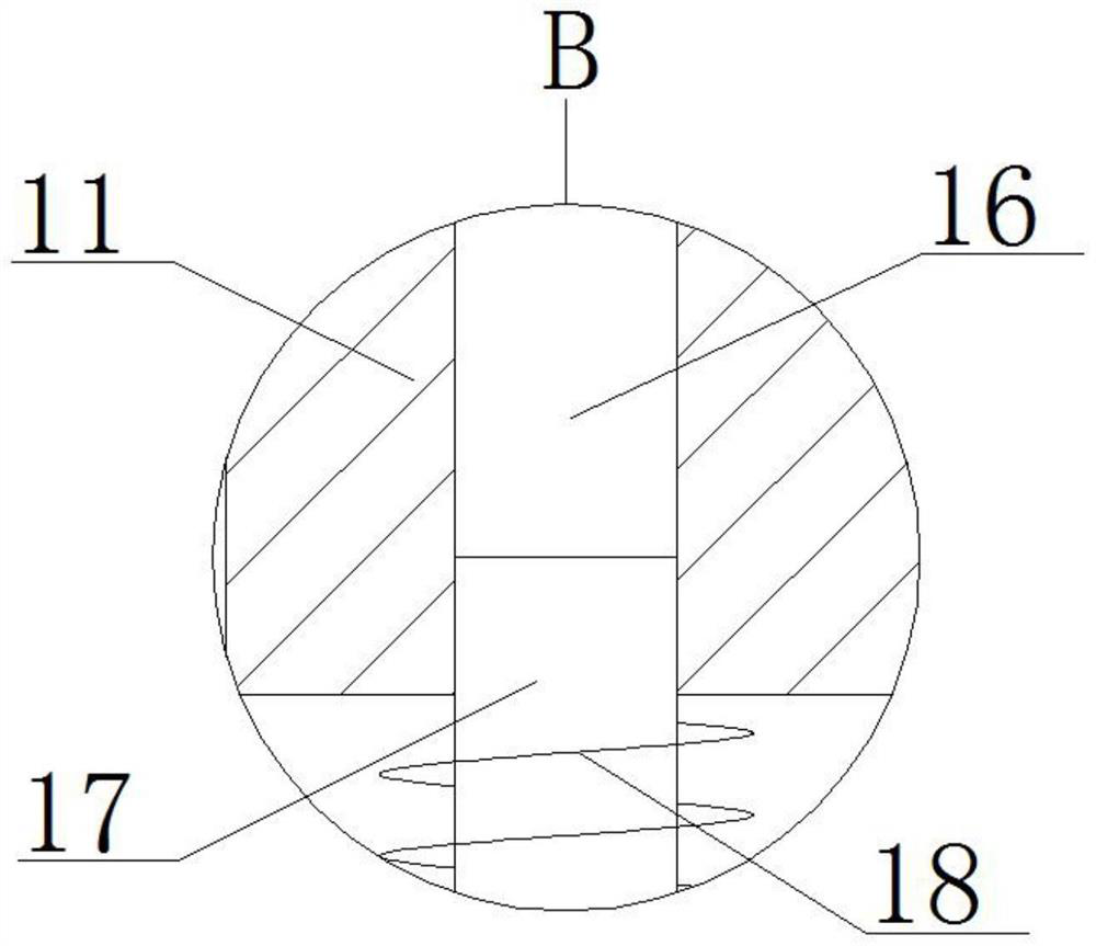
[0026] refer to Figure 1-5 A compression device after radial artery blood gas collection for a bedridden patient, comprising a mounting plate 1, the bottom of the mounting plate 1 is provided with two symmetrical first chutes 2, and struts 3 are slidably installed in the two first chutes 2 , the two struts 3 are provided with a clamping mechanism, the mounting plate 1 is provided with two symmetrical first empty slots 13, the bottom of the mounting plate 1 is provided with two symmetrical mounting slots, and the two mounting slots are respectively connected to the two The two first empty grooves 13 are communicated with each other, a toothed rod 14 is slidably installed in the two installation grooves, one end of the two toothed rods 14 is fixedly connected to the same fixing plate 11 by welding, and the bottom of the fixing plate 11 is provided with two symmetrical In the second chute 16, slide columns 17 are slidably installed in the two second slide slots 16, the two slide...

Embodiment 2

[0035] The difference from the first embodiment is that the clamping mechanism includes two fixing blocks 4, the outer sides of the two fixing blocks 4 are respectively connected with one end of the two supporting rods 3 by welding, and one side of the two fixing blocks 4 is A third chute is provided, and a slider 5 is slidably installed in the two third chute, one side of the two sliders 5 is fixedly connected with a plywood 6 by welding, and one side of the two plywood 6 is fixedly connected with a plywood 6. The rubber cushion 25, the other sides of the two sliding blocks 5 are fixedly connected with a first spring 7 by welding, and one end of the two first springs 7 is respectively connected with the inner wall of one side of the two third chutes by welding and fixedly connected, When the two splints 6 clamp the patient's wrist, the two first springs 7 can exert force on the two sliders 5 and the two splints 6 respectively.

[0036] Working principle, when in use, you can ...


PUM


Abstract

The invention belongs to the field of medical equipment, particularly relates to a compression device for a bedridden patient after radial artery blood gas collection, and aims to solve the problems that the time consumption is relatively long since hemostasis is carried out by pressing hemostatic cotton pieces by medical personnel after existing radial artery blood gas collection, and the medical personnel need to wait aside if the patient is not accompanied by family members; according to the technical scheme, the medical nursing device comprises a mounting plate, two symmetrical first sliding grooves are formed in the bottom of the mounting plate, supporting rods are slidably mounted in the two first sliding grooves, clamping mechanisms are arranged on the two supporting rods, two symmetrical first empty grooves are formed in the mounting plate, and the two first empty grooves are arranged in the mounting plate. In the using process, the wrist of a patient can be conveniently clamped, compression hemostasis can be effectively carried out on a wound, the two hands of medical staff are liberated, the working efficiency of the medical staff is improved, the structure is simple, and using is convenient.

Description

technical field [0001] The invention relates to the technical field of medical equipment, in particular to a compression device after radial artery blood gas collection for bedridden patients. Background technique [0002] The radial artery is one of the terminal branches of the brachial artery and is slightly smaller than the ulnar artery. The radial artery is about 21.2cm long and has an outer diameter of about 0.3cm at its origin. After the brachial artery is divided, it travels outward and downward, first between the brachioradialis and pronator teres, and then between the flexor carpi radialis and brachioradialis, to the lower end of the radius, obliquely crossing the abductor pollicis longus and brachius shortus From the deep surface of the extensor tendon to the back of the hand, it enters the nasopharyngeal fossa, and penetrates the first metacarpal space and enters the deep part of the palm. The radial artery is shallow between the lower end of the radius and the ...

Claims


Application Information

Patent Timeline
Patent Type & Authority Applications(China)
IPC IPC(8): A61B17/12A61B90/14
CPCA61B17/12A61B90/14A61B2017/12004
Inventor 刘静悦贾霞宫淑文
Owner 滨州医学院烟台附属医院
Learn More