Drilling blowout prevention efficient deslagging device and using method

A high-efficiency, blowout-proof technology, applied in the field of coal mine drilling and extraction, can solve problems that affect drilling safety, blockage of extraction main pipes, gas overrun, etc., to ensure life and health, ensure continuous construction, and reduce labor intensity Effect

Pending Publication Date: 2022-08-05
HUAINAN MINING IND GRP
View PDF0 Cites 0 Cited by
  • Summary
  • Abstract
  • Description
  • Claims
  • Application Information

AI Technical Summary

Problems solved by technology

[0002] The main method of gas control in some mines is drilling and drainage. As the depth of mine mining continues to increase, the pressure of coal seam gas is also increasing. drill safety
[0003] The traditional blowout preventer cannot automatically discharge slag. When the amount of cuttings exceeds the volume of the blowout preventer, it is necessary to stop drilling and turn off the negative pressure of the blowout preventer for cleaning. The coal passing through the drill hole cannot be continuous, and the pressure in the hole is easy to hold, resulting in delayed spray holes. resulting in gas overrun
Therefore, in order to increase the volume of the tank, the overall weight of the tank is more than 80 kg. It is difficult to transport and install underground, requiring the cooperation of multiple people; and the slag removal is mainly based on regular manual cleaning. When cleaning the blowout prevention, it is necessary to stop the pumping and affect the drilling. The holes are continuously constructed, and there is a risk of gas exceeding the limit caused by the nozzle holes during the process of stopping the pumping to clean the blowout preventer; the lagging and incomplete cleaning of the workers often leads to the blockage of the main pumping pipes, etc.

Method used


Image

  • Drilling blowout prevention efficient deslagging device and using method
  • Drilling blowout prevention efficient deslagging device and using method
  • Drilling blowout prevention efficient deslagging device and using method

Examples


Embodiment Construction

[0033] In order to make the purposes, technical solutions and advantages of the embodiments of the present invention clearer, the technical solutions in the embodiments of the present invention will be clearly and completely described below in conjunction with the embodiments of the present invention. Obviously, the described embodiments are part of the present invention. examples, but not all examples. Based on the embodiments of the present invention, all other embodiments obtained by those of ordinary skill in the art without creative efforts shall fall within the protection scope of the present invention.

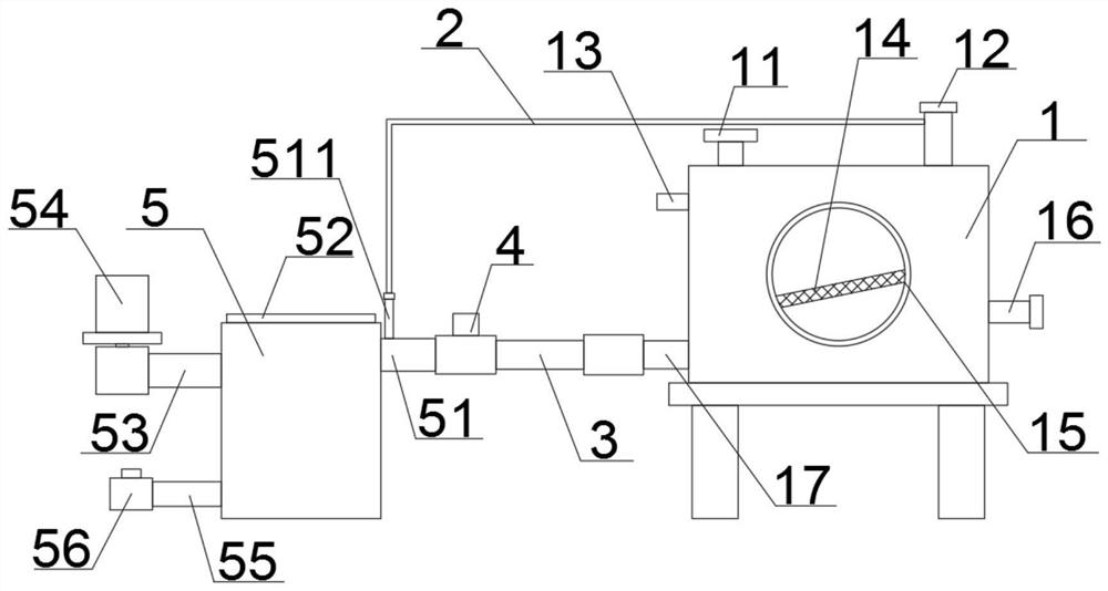
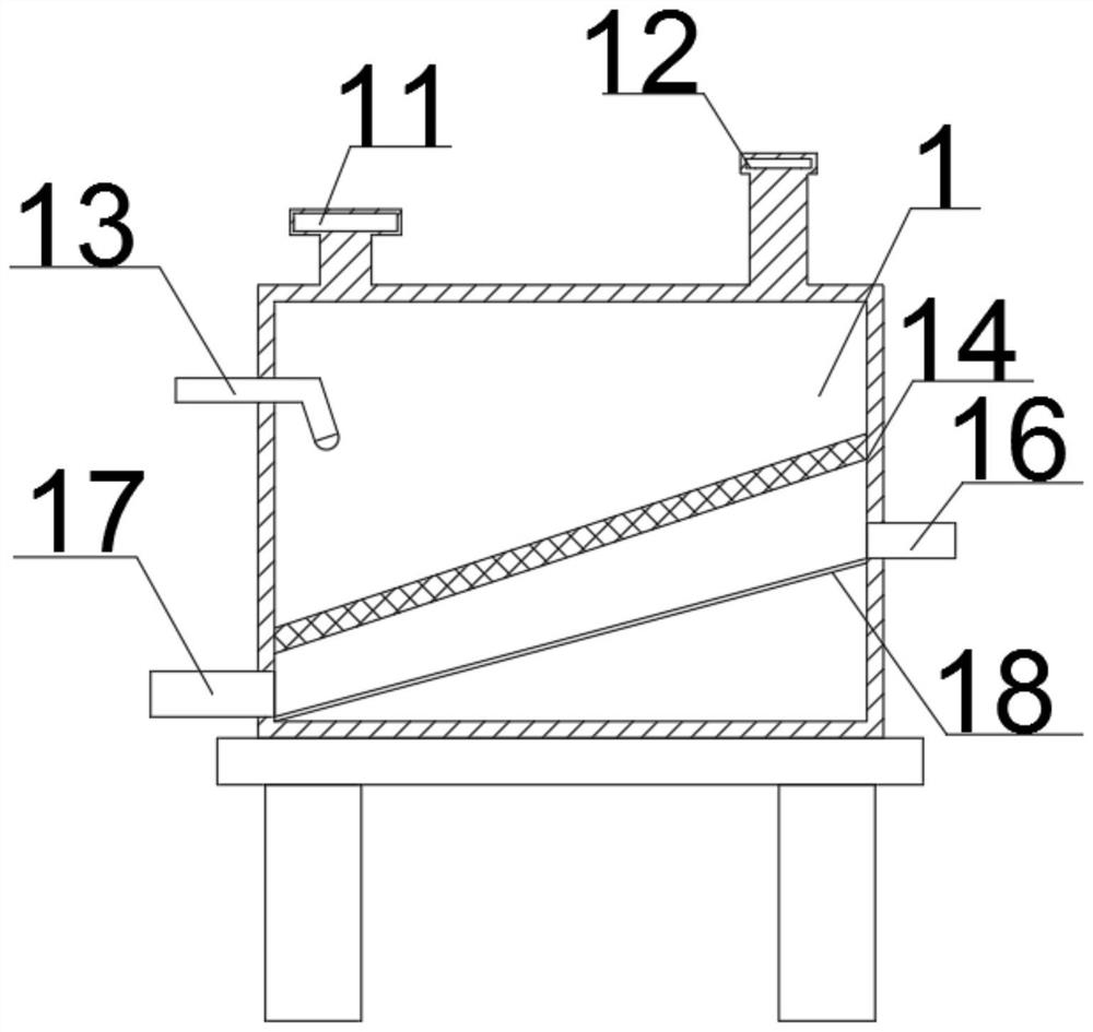
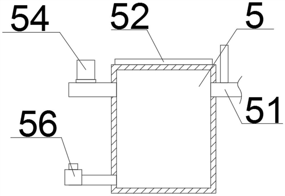
[0034] see figure 1 , This embodiment discloses a high-efficiency slag discharge device for drilling and blowout prevention, including a box body 1 , a hose 2 , a connecting pipe 3 , a first one-way valve 4 , and a tank body 5 .

[0035] Also see Figure 1-2 , 4. The box body 1 is a "rectangular" structure welded by steel plates with a thickness of 3mm. The box body 1...


PUM


Abstract

The invention discloses a drilling blowout prevention efficient deslagging device and a using method thereof.The drilling blowout prevention efficient deslagging device is characterized in that a first connector is connected with an extraction system through an extraction main pipe, the lower end of the right side of a box body is connected with a plurality of air inlet connectors, the air inlet connectors are all connected with a drilling machine orifice, and the lower end of the left side of the box body is connected with a first deslagging pipe; the outer side of the first slag discharging pipe is connected with a connecting pipe, the outer side of the connecting pipe is fixedly connected with a first one-way valve, the other end of the connecting pipe is connected with the tank body, the lower end of the right side of the tank body is connected with a second slag discharging pipe, and the outer side of the second slag discharging pipe is fixedly connected with a second one-way valve. Dust generated in the drilling process can be effectively removed, continuous extraction and automatic cleaning are achieved, the blowout prevention requirement is met, it is guaranteed that a pipeline is unblocked all the time, the multiple functions of blowout prevention, dust prevention and slag removal in drilling are integrated, and the practicability of the device is greatly improved.

Description

technical field [0001] The invention relates to drilling and drainage of coal mines, and more particularly to a high-efficiency slag discharging device for drilling and blowout prevention and a method for using the same. Background technique [0002] The main method of gas control in some mines is drilling and drainage. As the mining depth of the mine continues to increase, the gas pressure in the coal seam is also increasing. During the daily drilling construction process, the threat of gas blowholes always exists, which seriously affects the mining operation. Drill safely. [0003] The traditional blowout preventer cannot automatically discharge slag. After the amount of drill cuttings exceeds the volume of the blowout preventer, it is necessary to stop drilling and turn off the blowout preventer negative pressure for cleaning. Drilling through the coal cannot be continuous, and the pressure in the hole is easy to cause delayed injection holes. As a result, the gas exceed...

Claims


Application Information

Patent Timeline
Patent Type & Authority Applications(China)
IPC IPC(8): E21B43/34E21B43/18E21B41/00B01D50/60
CPCE21B43/35E21B43/18E21B41/005B01D50/60E21B43/006
Inventor 范永方亮张盛魏永平马建冯伟
Owner HUAINAN MINING IND GRP
Why Eureka
Try Eureka