Cable fault double-end positioning method based on continuous waves

A cable fault, double-ended positioning technology, applied in the fault location, information technology support system and other directions, can solve the problem that transmission is easily interfered by other noises, affect the results of positioning, affect the accuracy of positioning, etc., to improve the detection accuracy. , the effect of reducing reflected waves and eliminating interference

Pending Publication Date: 2022-08-05
海南电网有限责任公司乐东供电局
View PDF0 Cites 0 Cited by
  • Summary
  • Abstract
  • Description
  • Claims
  • Application Information

AI Technical Summary

Problems solved by technology

The principle is: use the characteristics of the constant wave velocity of traveling waves to record the time when the transient traveling wave reaches the measuring end for the first time, and the time when returning to the fault point and arriving at the measuring end after the first reflection, and then use the formula to calculate the fault location, so When using the single-ended positioning method, for the fault point that occurs near the transmitting end, due to the short reflection time, a certain blind area will be formed, which will affect the positioning result
For the fault point that occurs very far away from the transmitting end, due to the attenuation characteristics of the traveling wave itself, the reflected signal will be very weak, which will also affect the positioning accuracy; when using single-ended positioning, a pulse will be injected into the cable, the pulse Under the action of additional power at the fault point of the cable, there will be voltage and current waves close to the speed of light, but only one pulse will be injected into each test, and only one reflected wave will be returned. Interference from other noises; when single-ended positioning is used, a detection pulse will be injected into the cable, the detection pulse bandwidth sent during the test is limited, the time width is very narrow, the detection accuracy is not high, and it is easily affected by noise

Method used


Image

  • Cable fault double-end positioning method based on continuous waves
  • Cable fault double-end positioning method based on continuous waves
  • Cable fault double-end positioning method based on continuous waves

Examples


Embodiment Construction

[0047] The principles and features of the present invention will be described below with reference to the accompanying drawings. The enumerated embodiments are only used to explain the present invention, but not to limit the scope of the present invention.

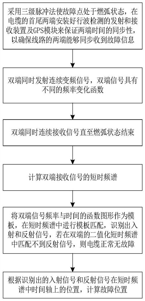
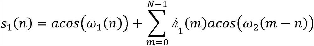
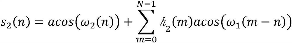
[0048] refer to figure 1 , the present invention provides a continuous wave-based double-ended locating method for cable faults, the method comprising the following steps:

[0049] Step 1: When the fault point is in the arcing state by the three-level pulse method, install the traveling wave detection device, the traveling wave receiving device and the GPS module at the beginning and end of the cable to ensure the synchronization of the time at the beginning and end of the cable. Both ends of the line can receive fault information synchronously;

[0050]Exemplarily, when a cable fails, an equivalent circuit analysis is performed on the cable, and the fault point can be regarded as having an equivalent capacitance. When t...


PUM


Abstract

The invention provides a cable fault double-end positioning method based on continuous waves, and the method comprises the steps: guaranteeing the time synchronization of the head and tail ends of a cable through installing a traveling wave detection device, a traveling wave receiving device and a GPS module at the head and tail ends of the cable, so as to guarantee that the two ends of a cable line can synchronously receive fault information; according to the method, reflected waves at the two ends of the cable can be reduced, all detection data can be effectively utilized through short-time spectrum matching, interference resistance is high, interference of opposite-end transmitting signals can be effectively eliminated through the design of a frequency change function, spectrum images of received signals contain sufficient information, and a better basis can be provided for follow-up fault recognition.

Description

technical field [0001] The invention relates to the technical field of cable fault detection, in particular to a method for locating cable faults at both ends based on continuous waves. Background technique [0002] The current cables in power transmission will fail after being damaged by external force or aging for a long time. When the fault occurs on the cable, it is particularly important to find the fault location accurately and quickly. The most commonly used method at present is the single-ended positioning method, also known as the single-ended traveling wave ranging method. The principle is: using the constant velocity of traveling wave, record the time when the transient traveling wave reaches the measuring end for the first time and the time when the return fault point reaches the measuring end after the first reflection, and then use the formula to calculate the fault location, so When the single-end positioning method is adopted, for the fault point near the tr...

Claims


Application Information

Patent Timeline
IPC IPC(8): G01R31/08
CPCG01R31/088G01R31/083Y04S10/52
Inventor 刘鹏程冯杰孟春旅孙源陈运锐陈泰谷陈俞伊陈泽豪黎立夫林正巧
Owner 海南电网有限责任公司乐东供电局
Why Eureka
Try Eureka