
Wafer drying machine and implementation method

A realization method and wafer technology, applied in the manufacturing of electrical components, circuits, semiconductor/solid-state devices, etc., can solve the problems of wafer scratches, unqualified wafer surface quality, etc., and achieve the effect of rapid drying

Pending Publication Date: 2022-08-05
ZHICHENG SEMICON EQUIP TECH (KUNSHAN) CO LTD
View PDF0 Cites 0 Cited by
  • Summary
  • Abstract
  • Description
  • Claims
  • Application Information

AI Technical Summary

Problems solved by technology

When the staff wipes the wafer, it is easy to scratch the surface of the wafer, which will cause the surface quality of the wafer to be unqualified and scrapped

Method used


Image

  • Wafer drying machine and implementation method
  • Wafer drying machine and implementation method
  • Wafer drying machine and implementation method

Examples


Embodiment 1

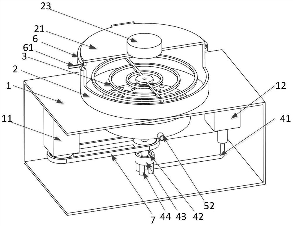
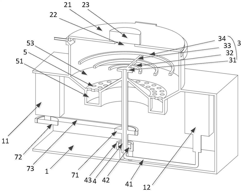
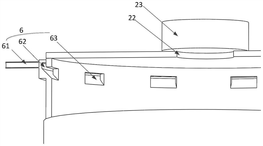
[0050] like Figure 1-2 As shown, a wafer drying machine includes a box body 1 and a barrel body 2 arranged on the top of the box body 1. A barrel cover 21 is hinged on the top of the barrel body 2, and a camera 23 with a lens facing downward is arranged in the middle of the barrel cover 21. The middle part of the cylinder body 2 is provided with a tray 3, the bottom of the tray 3 is connected with a rotating shaft 4, and the lower end of the rotating shaft 4 is rotatably connected to the bottom wall of the box body 1; the bottom of the cylinder body 2 is provided with a water outlet 5, and the bottom of the water outlet 5 is provided with a ring The water tank 51 is provided with a drainage pipe 52 on the water tank 51; the outer wall of the cylinder body 2 is provided with an annular air passage 6 that is conductive with the inner side of the cylinder body 2, and the air passage 6 is provided with a blowing pipe 61, and the blowing pipe 61 is connected with a blower; A power...

Embodiment 2

[0057] like Figure 4 As shown, a method for implementing a wafer spinner based on Embodiment 1 includes the following steps:

[0058] (1) Open the cylinder cover, place the wafer on the tray, and start the vacuum pump to adsorb the wafer;

[0059] (2) Close the cylinder cover, and start the power member to drive the shaft to rotate through the transmission assembly;

[0060] (3) Drive the tray to rotate through the rotating shaft, the wafer rotates with the drag tray, and the water droplets on the wafer are thrown onto the inner wall of the cylinder based on centrifugal force;

[0061] (4) The air is blown into the air path along the air blowing pipe by the blower, and the air is blown onto the wafer;

[0062] (5) The water droplets are introduced into the water tank through the water outlet hole and discharged through the drain pipe;

[0063] (6) When the preset time is reached, the power element and the blower are turned off, and the image data of the wafer is collected ...


PUM


Abstract

The invention provides a wafer drying machine and an implementation method, the drying machine comprises a box body and a cylinder body arranged at the top of the box body, a cylinder cover is hinged to the top of the cylinder body, and a camera with a downward lens is arranged in the middle of the cylinder cover; a rotating shaft is connected to the bottom of the tray, and the lower end of the rotating shaft is rotationally connected to the bottom wall of the box body; a water outlet is formed in the bottom of the barrel, an annular water tank is arranged at the bottom of the water outlet, and a drainage pipe is arranged on the water tank; an annular gas path communicated with the inner side of the cylinder body is arranged on the outer wall of the cylinder body, a gas blowing pipe is arranged on the gas path, and a blower is connected to the gas blowing pipe; a power piece and a vacuum pump are arranged in the box body, and a transmission assembly is arranged on the rotating shaft and connected to the power piece. One end of the air pipe is connected to the middle of the tray, and the other end of the air pipe is connected to the vacuum pump; according to the invention, the wafer can be quickly spin-dried without generating scratches.

Description

technical field [0001] The invention belongs to the technical field of semiconductor processing, and in particular relates to a wafer drying machine and a realization method. Background technique [0002] Wafer refers to the silicon wafer used in the manufacture of silicon semiconductor integrated circuits. Because of its circular shape, it is called a wafer. On the silicon wafer, it can be processed into various circuit element structures and become electronic devices with specific electrical functions. component products. [0003] When the wafer is processed, the wafer is usually protected by a film, and a ring-shaped support plate made of magnetic metal is bonded to the edge of the protective film, so that the protective film is stretched tightly, and then the wafer is placed After entering the dicing machine, the back of the wafer is mechanically cut. Since the wafer needs to be sprayed, cooled and cleaned during the cutting process, the wet wafer is manually wiped clea...

Claims


Application Information

Patent Timeline
IPC IPC(8): H01L21/67
CPCH01L21/67034
Inventor 于瑶吴求
Owner ZHICHENG SEMICON EQUIP TECH (KUNSHAN) CO LTD
Learn More