
Intelligent control device for electromechanical equipment

A technology of intelligent control and electromechanical equipment, applied in the direction of comprehensive factory control, support structure installation, cooling/ventilation/heating transformation, etc., can solve problems such as inconvenient installation, complicated wiring, high failure rate, etc., to reduce temperature and improve practicability Effect

Pending Publication Date: 2022-08-05
YELLOW RIVER CONSERVANCY TECHN INST
View PDF1 Cites 0 Cited by
  • Summary
  • Abstract
  • Description
  • Claims
  • Application Information

AI Technical Summary

Problems solved by technology

The use of these electrical components requires internal wiring, complex wiring, high failure rate, large controller volume, and inconvenient installation. At present, a new type of intelligent positive pressure controller (public number CN109451687A) has been disclosed through retrieval of Chinese patents. The integrated control unit replaces the traditional electrical components such as air switch, intermediate relay and time relay. It has a compact structure and is easy to install. There is no need for wiring inside the control unit. Internal parameters to meet different customer requirements, high intelligence, low commissioning and maintenance costs, wide application range, because the patent uses the control unit to bring up the original electrical components, which will make the internal structure of the control unit compact together, when When the control unit is in normal operation, it will generate a lot of heat. Even if the patent uses a cooling fan to relieve heat dissipation, and because the protection level of the explosion-proof controller needs to reach IP66, the inside of the explosion-proof controller will be sealed at this time. It has accumulated in the explosion-proof controller for a long time, and the control unit cannot be effectively dissipated, which is a problem that needs to be solved at present

Method used


Image

  • Intelligent control device for electromechanical equipment
  • Intelligent control device for electromechanical equipment
  • Intelligent control device for electromechanical equipment

Examples


Embodiment Construction

[0028] The technical solutions in the embodiments of the present invention will be clearly and completely described below with reference to the accompanying drawings in the embodiments of the present invention. Obviously, the described embodiments are only a part of the embodiments of the present invention, rather than all the embodiments. Based on the embodiments of the present invention, all other embodiments obtained by those of ordinary skill in the art without creative efforts shall fall within the protection scope of the present invention.

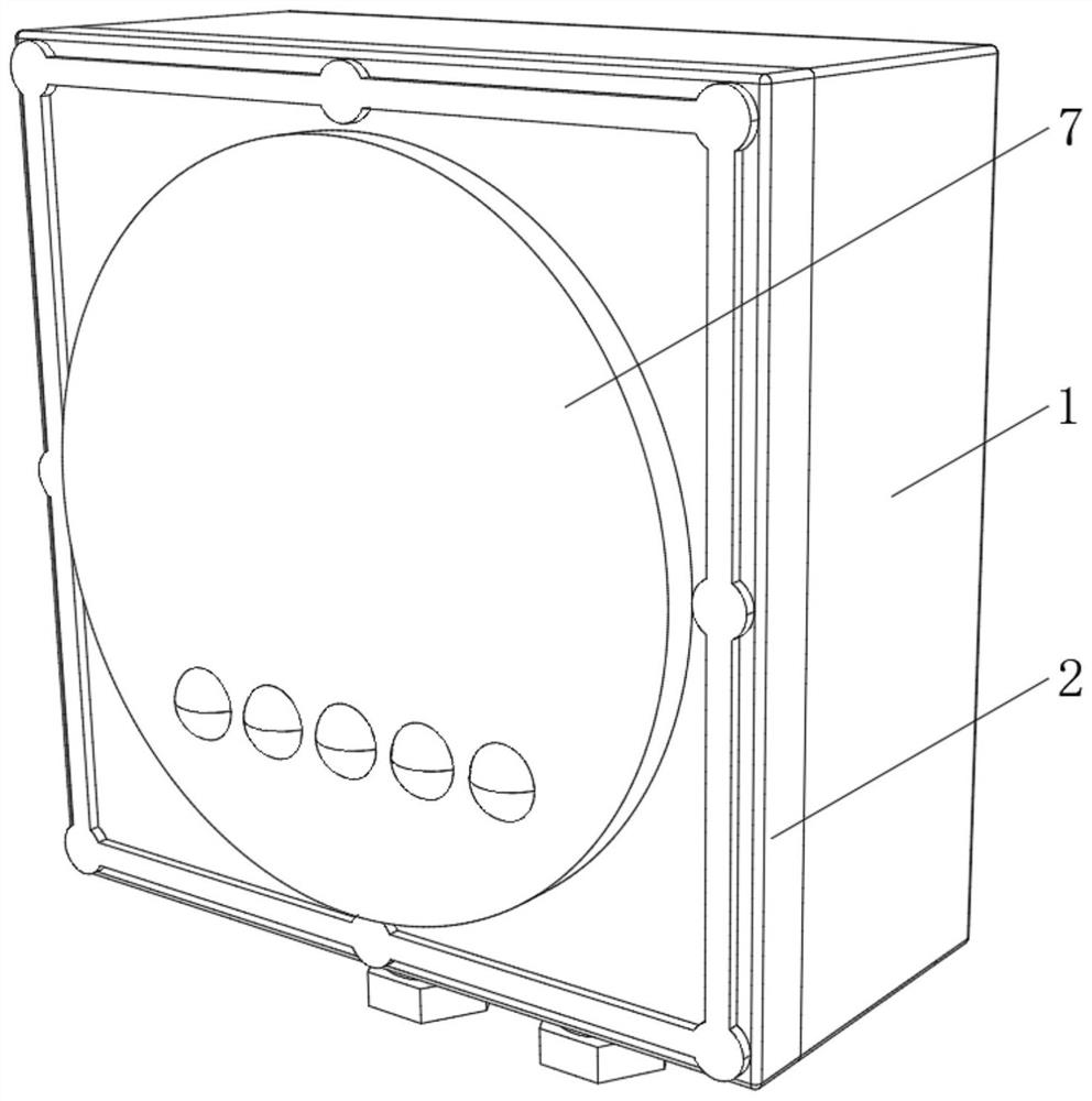
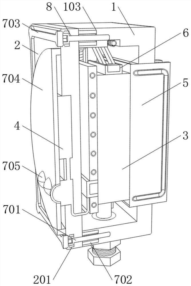
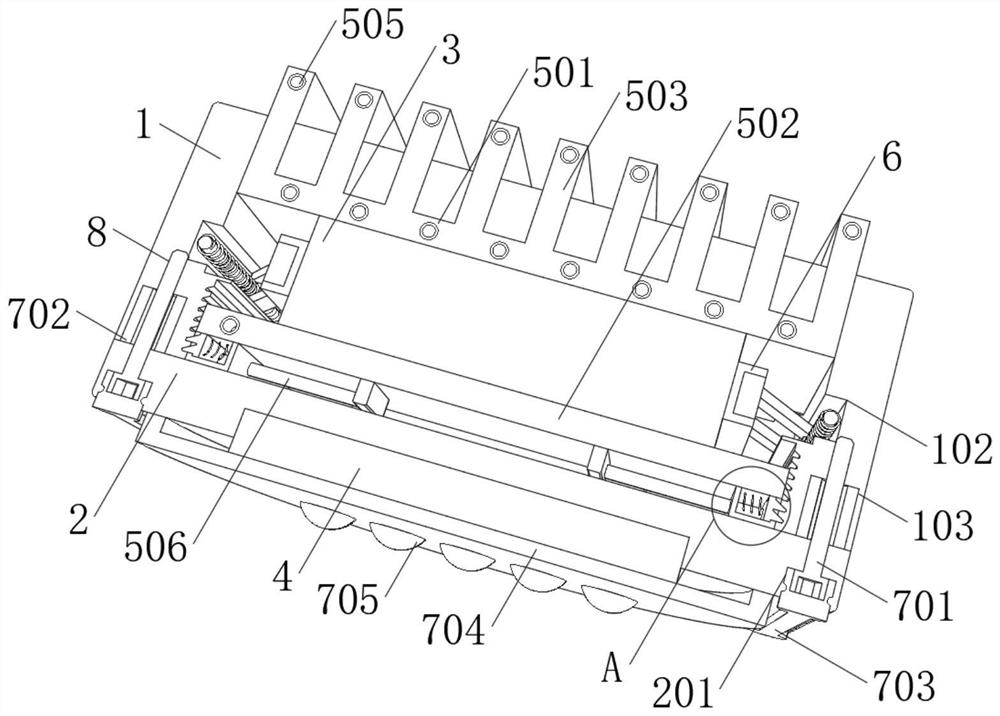
[0029] When implementing: as Figure 1-8 As shown, an intelligent control device for electromechanical equipment includes: a casing 1, a front end of the casing 1 is fixedly connected with a protective panel 2, a control unit 3 is mounted on the inner bottom wall of the casing 1, and the front end of the control unit 3 is electrically connected There is an operation unit 4 , and the front end of the operation unit 4 penetrates to the...


PUM


Abstract

The invention relates to the technical field of explosion-proof controllers, in particular to an intelligent control device for electromechanical equipment, which comprises a shell, the front end of the shell is fixedly connected with a protection panel, the inner bottom wall of the shell is provided with a control unit, the front end of the control unit is electrically connected with an operation unit, and the front end of the operation unit is electrically connected with a power supply. The front end of the operation unit penetrates to the outside of the protection panel; the cooling device is used for reducing the temperature of the control unit and is mounted on the surface of the control unit; by arranging the cooling device, when the control unit operates normally, heat conduction oil can continuously absorb heat emitted by the control unit through a heat conduction pipe and a fixed heat conduction plate or a movable heat conduction frame, so that the control unit can operate in a low-temperature state all the time, the overheating probability of the control unit is effectively reduced, and the service life of the control unit is prolonged. Meanwhile, the micro liquid conveying pump continuously pushes the heat conduction oil to move, and the heat conduction oil enters along the rear heat conduction pipe.

Description

technical field [0001] The invention relates to the technical field of explosion-proof controllers, in particular to an intelligent control device for electromechanical equipment. Background technique [0002] Industries that require a high safety factor such as coal mines, chemicals, petroleum or electric power mostly use explosion-proof controllers as intelligent control devices for electromechanical equipment. When the operation index of electromechanical equipment reaches or exceeds the upper limit set by the explosion-proof controller, the explosion-proof controller will automatically Cut off the circuit to make the equipment stop to play an automatic protection role. The existing positive pressure explosion-proof controllers mainly use electrical components such as air switches, intermediate relays and time relays. The use of these electrical components requires internal wiring, complex wiring, high failure rate, large controller volume, and inconvenient installation. ...

Claims


Application Information

Patent Timeline
Patent Type & Authority Applications(China)
IPC IPC(8): H05K7/20H05K7/14
CPCH05K7/20218H05K7/2039H05K7/1401Y02P90/02
Inventor 沈艳河杨彦涛宋新范龙史龙飞王兵维
Owner YELLOW RIVER CONSERVANCY TECHN INST
Learn More