
Electronic and mechanical double-control battery pack fire extinguishing system

A technology for a fire extinguishing system and a battery pack, applied in the field of a battery pack fire extinguishing system, can solve the problem that the battery pack cannot extinguish fire, and achieve the effects of simplifying the structure, reducing fire accidents, and increasing the probability of fire extinguishing

Active Publication Date: 2022-08-09
河南宏硕电气有限公司
View PDF7 Cites 0 Cited by
  • Summary
  • Abstract
  • Description
  • Claims
  • Application Information

AI Technical Summary

Problems solved by technology

[0006] The purpose of the present invention is to provide an electronic and mechanical double-controlled battery pack fire extinguishing system to solve the problem that the battery pack in the prior art may not be able to extinguish the fire due to failure of electronic components

Method used


Image

  • Electronic and mechanical double-control battery pack fire extinguishing system
  • Electronic and mechanical double-control battery pack fire extinguishing system
  • Electronic and mechanical double-control battery pack fire extinguishing system

Examples


Embodiment 1

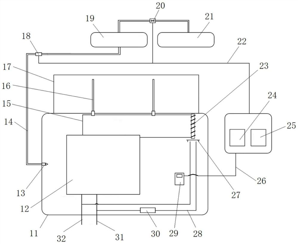
[0039] like figure 1As shown, the electronic and mechanical dual-control battery pack fire extinguishing system includes a casing 11, an electronic fire extinguishing device, a mechanical fire extinguishing device and a controller. The casing 11 is provided with a battery pack 12 and a temperature sensor 29, and the temperature sensor 29 is used for monitoring the casing. temperature inside the body 11. The battery pack 12 includes devices such as battery cells and a battery control board connected in series, and the casing 11 and the battery pack 12 together form a battery pack.

[0040] In this embodiment, the battery pack 12 is connected with the main loop positive line 31 and the main loop negative line 32, and the main loop positive line 31 and the main loop negative line 32 are respectively connected with two adjacent battery packs, so as to realize the connection between the battery packs. concatenation between.

[0041] In this embodiment, the electronic fire extingu...

Embodiment 2

[0058] The difference between this embodiment and Embodiment 1 is that, in Embodiment 1, the bypass protection circuit realizes bypass protection by melting a fusible conductor. In this embodiment, the bypass protection circuit realizes the bypass protection by controlling the electronic switch by the controller.

Embodiment 3

[0060] The difference between this embodiment and Embodiment 1 is that in Embodiment 1, the fusible body of the nozzle on the second nozzle is a fusible conductor on the series circuit. In this embodiment, the fusible body of the spout on the second nozzle and the fusible conductor on the series circuit are arranged independently. At this time, the fusible body of the nozzle on the second nozzle can be a fusible conductor or a fusible conductor. non-conductor.


PUM


Abstract

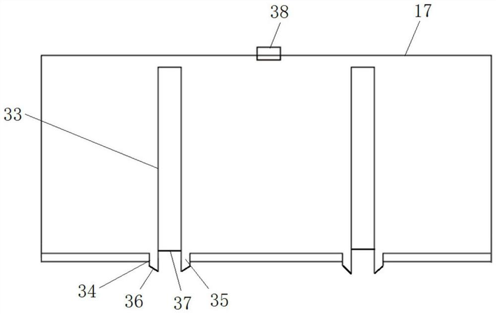
The invention relates to the field of battery pack fire extinguishing, in particular to an electronic and mechanical double-control battery pack fire extinguishing system. The electronic and mechanical double-control battery pack fire extinguishing system comprises a shell, an electronic fire extinguishing device and a controller, wherein a battery pack and a temperature sensor are arranged in the shell; the electronic fire extinguishing device comprises a first storage container and a first spray head connected with the first storage container, and a nozzle of the first spray head is located in the shell; when the temperature in the shell reaches a first set temperature, the controller controls the electronic fire extinguishing device to spray a fire extinguishing agent into the shell; the mechanical fire extinguishing device comprises a second storage container and a second spray head connected to the bottom of the second storage container, the second storage container is fixed to the outer side of the top of the shell, and a nozzle of the second spray head is located in the shell; and a nozzle fusible body for blocking a nozzle of the second spray head is arranged on the second spray head, and the nozzle fusible body is molten when the temperature in the shell reaches a second set temperature, so that the fire extinguishing agent in the second storage container is sprayed into the shell from the nozzle of the second spray head.

Description

technical field [0001] The invention relates to the field of battery pack fire extinguishing, in particular to an electronic and mechanical dual control battery pack fire extinguishing system. Background technique [0002] With the proposal of the country's overall environmental strategy, power batteries and energy storage batteries will usher in a new peak of development. At present, chemical energy storage represented by lithium-ion batteries is widely used. However, the compounds used in chemical batteries have strong instability, and there is a certain probability of causing fire hazards in production and life, resulting in casualties and property losses. [0003] The thermal runaway of chemical batteries based on different compounds leads to different fires. However, its comprehensive characteristics will generate heat accumulation during use, resulting in thermal runaway and eventually fire. From this point of view, effective monitoring of thermal runaway during the...

Claims


Application Information

Patent Timeline
Patent Type & Authority Applications(China)
IPC IPC(8): A62C3/16A62C31/02A62C31/28A62C37/40A62C37/48
CPCA62C3/16A62C31/02A62C31/28A62C37/40A62C37/48Y02E60/10
Inventor 鲍忠余
Owner 河南宏硕电气有限公司
Learn More