Liftable new energy charging pile based on Internet

A new energy and Internet technology, applied in charging stations, electric vehicle charging technology, electric vehicles, etc., can solve the problems of freezing, the gun head cannot be directly inserted into the socket, etc., and achieve the effect of preventing freezing.

Pending Publication Date: 2022-08-09
深圳市天赋新能源科技有限公司
View PDF0 Cites 0 Cited by
  • Summary
  • Abstract
  • Description
  • Claims
  • Application Information

AI Technical Summary

Problems solved by technology

[0003] In winter rainy and snowy weather, the driver unplugs the gun head on the charging pile and plugs it into the charging port of the car, but at this time the rain and snow will fall into the socket on the charging pile. The rain and snow insid

Method used


Image

  • Liftable new energy charging pile based on Internet
  • Liftable new energy charging pile based on Internet
  • Liftable new energy charging pile based on Internet

Examples


Embodiment 1

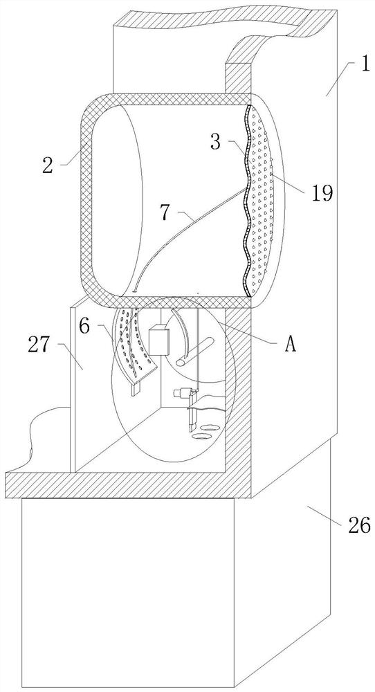
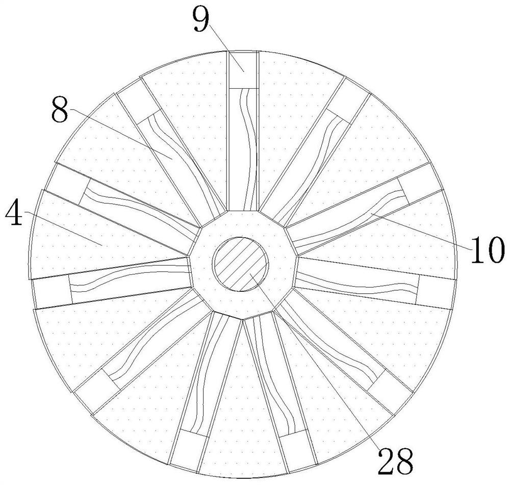
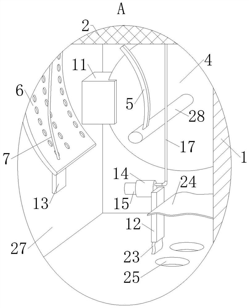
[0030] like Figure 1 to Figure 3 As shown in the figure, an Internet-based liftable new energy charging pile according to the embodiment of the present invention includes a casing 1, a telescopic rod 26 is fixedly installed on the bottom wall of the casing 1, and the casing 1 is fixed inside An intubation tube 2 that communicates with the outside world is inserted, an elastic member 3 is fixedly installed on the intubation tube 2, a rotating shaft 28 is rotatably installed in the casing 1, and a turntable 4 is fixedly installed on the rotating shaft 28, and the turntable 4 is provided with a drive assembly for driving the rotating shaft 28 to rotate, a push rod 5 is vertically fixed on the rotating shaft 28, a counterweight plate 6 is hinged on the bottom wall of the intubation tube 2, and the counterweight plate 6 is fixed on the A connecting rope 7 running through the cannula 2 is installed, and the other end of the connecting rope 7 is fixedly connected with the elastic me...

Embodiment 2

[0040] like Image 6 , Figure 7 As shown in Comparative Example 1, another embodiment of the present invention is: the blocking ball 22 includes an outer ball 2201 and a ball 2202, and the outer wall of the outer ball 2201 is evenly provided with air flow grooves, and the outer The ball 2201 is provided with a groove, the ball 2202 is movably embedded in the groove, and the second elastic rope 21 is fixedly connected with the ball 2202; by connecting the second elastic rope 21 and the ball 2202, the outer ball 2201 It can rotate normally, so when the gas discharged from the cavity is blown into the guide groove on the outer ball 2201, the outer ball 2201 rotates rapidly under the action of the impact force of the air flow, and the snow falling on the outer ball 2201 can be removed during the rotation process. The water is thrown away, and the snow water has a certain impact force and can overcome the wind force, which plays the role of drying the elastic member 3 quickly.

...


PUM


Abstract

The invention belongs to the technical field of charging piles, and particularly relates to an internet-based liftable new energy charging pile, which comprises a shell, a telescopic rod is fixedly mounted on the bottom wall of the shell, an insertion pipe communicated with the outside is fixedly inserted in the shell, an elastic piece is fixedly mounted on the insertion pipe, a rotating shaft is rotatably mounted in the shell, and the rotating shaft is fixedly connected with the telescopic rod. A rotating disc is fixedly mounted on the rotating shaft, and a driving assembly for driving the rotating shaft to rotate is arranged on the rotating disc; the elastic piece is pulled by the counterweight plate through the connecting rope, so that the elastic piece deforms, after the counterweight plate is separated from the push rod, the counterweight plate rotates reversely around the hinge point and resets under the action of gravity, at the moment, the connecting rope does not apply pulling force to the elastic piece any more, and therefore the elastic piece begins to reset, and after the elastic piece resets, the elastic piece shakes back and forth; in the shaking process, snow water drifting on the surface of the elastic piece is bounced off, so that the surface of the elastic piece can be kept dry, and the effect of preventing the elastic piece from freezing is achieved.

Description

technical field [0001] The invention belongs to the technical field of charging piles, in particular to an Internet-based elevating new energy charging pile. Background technique [0002] Vehicle charging is an important link in the development of new energy vehicles. The insufficiency of charging system infrastructure will directly restrict the industrial development of new energy vehicles. With the advancement of technology, charging pile equipment that can charge new energy vehicles has begun to appear in recent years. Its input end is directly connected to the AC power grid, and the output end is equipped with a charging plug for charging new energy vehicles. [0003] In the rainy and snowy weather in winter, the driver will unplug the gun on the charging pile and insert it into the charging port of the car, but at this time the rain and snow will fall to the inside of the socket on the charging pile. Due to the low temperature in winter, it will fall to The rain and s...

Claims


Application Information

Patent Timeline
IPC IPC(8): B60L53/31B60L53/16
CPCB60L53/31B60L53/16Y02T90/14
Inventor 邝柳明
Owner 深圳市天赋新能源科技有限公司
Why Eureka
Try Eureka