Asphalt storage tank energy-saving heating device for waterproof coiled material
A waterproof membrane and heating device technology, applied in the field of asphalt, can solve problems such as blockage of the discharge pipe, waste of heat, and affect the convenient discharge of the device, so as to save resources and increase the output speed of asphalt
- Summary
- Abstract
- Description
- Claims
- Application Information
AI Technical Summary
Problems solved by technology
Method used
Image
Examples
Embodiment 1
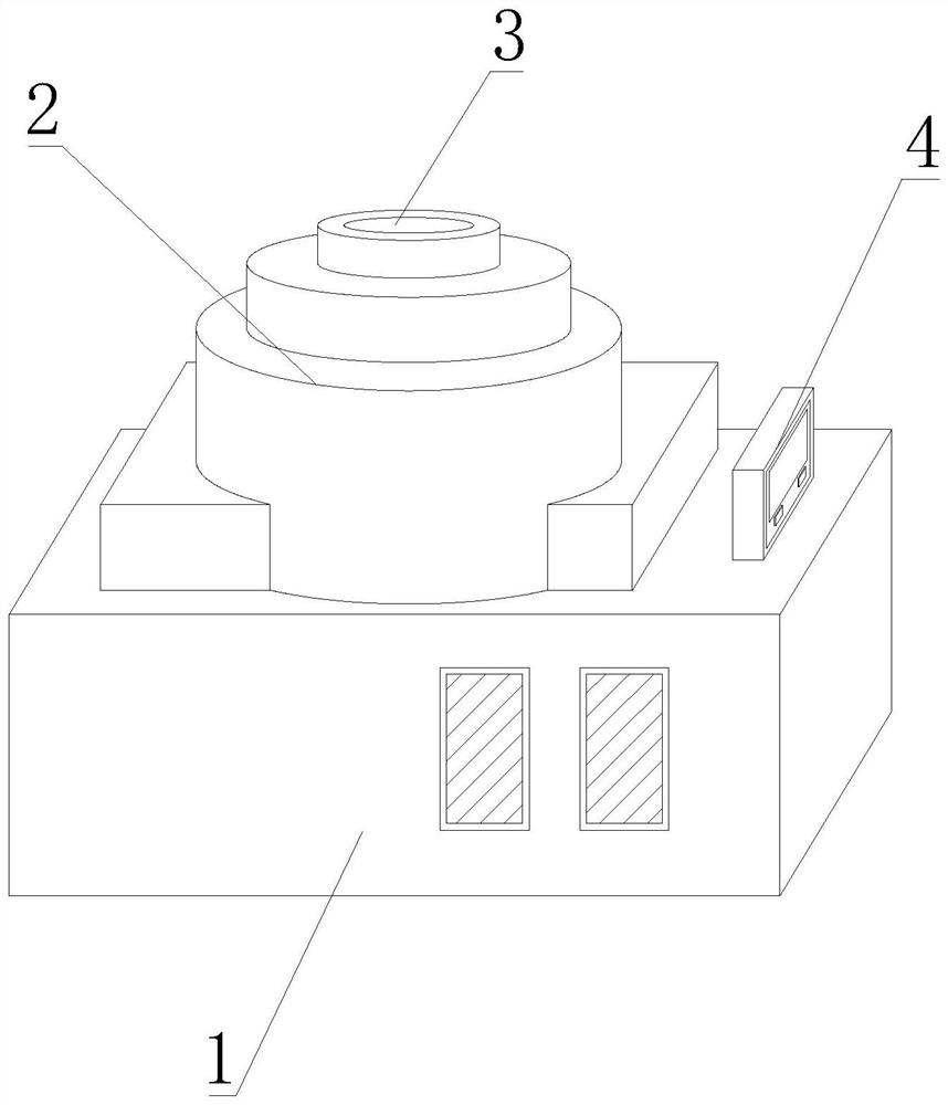
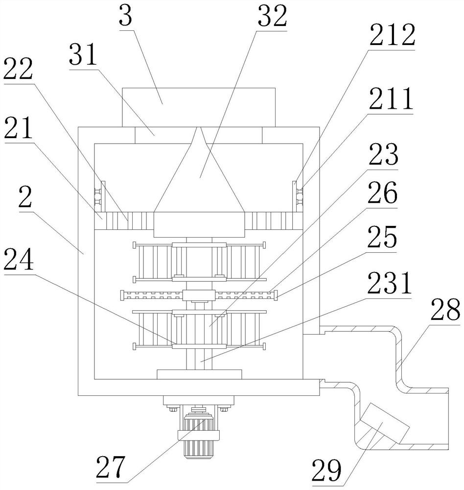
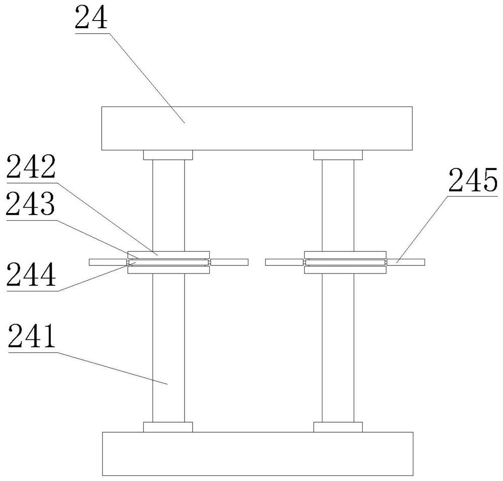
[0035] like Figure 1-8 As shown, the present invention provides an energy-saving heating device for an asphalt storage tank for a waterproofing membrane, comprising a device box 1, a storage tank 2, a material injection pipe 3 and a control panel 4, and one end of the top of the device box 1 is fixedly sleeved with a storage tank 2. The top of the storage tank 2 is provided with a material injection pipe 3, the other end of the top of the device box 1 is fixedly installed with a control panel 4, the interior of the storage tank 2 is fixedly installed with a flat baffle 21, and the bottom of the baffle 21 is movably connected with a center Shaft 23, the bottom of the central shaft 23 is fixedly connected with a power motor 27, the upper and lower ends of the central shaft 23 are fixedly installed with a stirring frame 24, the inner side of the stirring frame 24 is fixedly installed with a stirring rod 241, and the outer side of the central shaft 23 is located in the stirring fr...
Embodiment 2
[0038] like Figure 1-8 As shown, on the basis of Embodiment 1, the present invention provides a technical solution: preferably, a discharge pipe 28 is fixedly installed on one side of the bottom of the storage tank 2, and a flow guide is fixedly installed at the bottom of the inner cavity of the discharge pipe 28 Plate 29, an inclined baffle 290 is fixedly installed at one end of the inner cavity of the baffle plate 29, a guide groove 291 is opened on the inner side of the baffle plate 29, and a fixed column 292 is arranged inside the guide groove 291. A rotating shaft 293 is provided on the outside, a rotating plate 294 is fixedly installed on the outside of the rotating shaft 293, the bottom of the fixed column 292 extends to the bottom of the deflector 29 and is fixedly connected with a rotating gear 2921, and the side of the rotating gear 2921 is engaged with a transmission gear 2922 , a drive motor 2923 is fixedly connected to the inside of the transmission gear 2922 . ...
Embodiment 3
[0041] like Figure 1-8 As shown, on the basis of Embodiment 1, the present invention provides a technical solution: preferably, moving grooves 2941 are provided on both sides of the top of the rotating plate 294, and a sliding block 2942 is movably installed inside the moving groove 2941, and the sliding block 2942 One side of the bottom is fixedly connected with a telescopic rod, the other end of the telescopic rod is fixedly installed inside the moving groove 2941, the side of the sliding block 2942 is fixedly connected with a scraper 2943, and the top of one side of the scraper 2943 is fixedly installed with a friction plate 2944 , one end of the rotating plate 294 is provided with a rubber pad 2945, the bottom of the rubber pad 2945 is fixedly connected with an elastic pressure column 2946, the outer side of the elastic pressure column 2946 is provided with an elastic wire 2947, and the bottom of the elastic pressure column 2946 is fixedly installed with a squeeze pad 2948...
PUM
 Abstract
Description
Claims
Application Information
 - R&D
- Intellectual Property
- Life Sciences
- Materials
- Tech Scout
- Unparalleled Data Quality
- Higher Quality Content
- 60% Fewer Hallucinations
Browse by: Latest US Patents, China's latest patents, Technical Efficacy Thesaurus, Application Domain, Technology Topic, Popular Technical Reports.
© 2025 PatSnap. All rights reserved.Legal|Privacy policy|Modern Slavery Act Transparency Statement|Sitemap|About US| Contact US: help@patsnap.com


