Hot air anti-icing structure of aero-engine rectifying support plate

A technology of aero-engines and rectifying struts, which is applied in the direction of machines/engines, air transportation, mechanical equipment, etc., can solve the problems of large differences in hot air temperature and flow, insufficient strength of anti-icing components, and large differences in surface temperature, etc., to achieve High heat utilization efficiency, good anti-icing effect, strong convective heat transfer ability

Active Publication Date: 2022-08-09
NANJING UNIV OF AERONAUTICS & ASTRONAUTICS
View PDF7 Cites 2 Cited by
  • Summary
  • Abstract
  • Description
  • Claims
  • Application Information

AI Technical Summary

Problems solved by technology

[0004] At present, the anti-icing structure is mainly a jet impingement-air film composite heat exchange structure, which has a good heat exchange effect, but for the load-bearing parts at the front end of the engine and the anti-icing parts with a large span span and small thickness, the leading edge wall Air film hole structure will lead to insufficient strength of anti-icing components
Secondly, due to the large span span, the temperature and flow of hot air at the upper end and the lower end differ greatly, which will lead to a large difference in surface temperature between the support plate and the lower end. Therefore, a more in-depth design of the anti-icing structure is required to meet the anti-icing requirements Under the premise of taking into account the strength of components and the uniformity of protection, etc.

Method used


Image

  • Hot air anti-icing structure of aero-engine rectifying support plate
  • Hot air anti-icing structure of aero-engine rectifying support plate
  • Hot air anti-icing structure of aero-engine rectifying support plate

Examples


Embodiment Construction

[0032] The present invention will be further described below in conjunction with the accompanying drawings. Obviously, the described embodiments are some, but not all, embodiments of the present invention. Based on the embodiments of the present invention, all other embodiments obtained by those of ordinary skill in the art without creative efforts shall fall within the protection scope of the present invention.

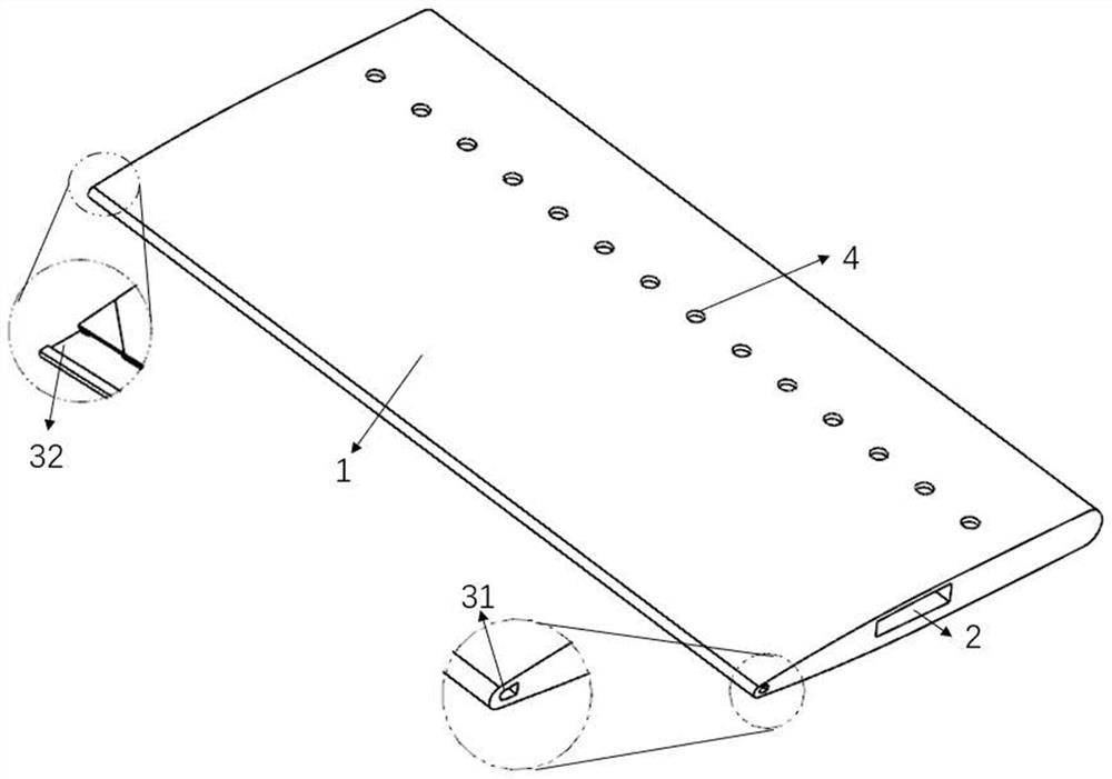
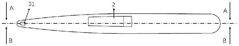
[0033] like figure 1 As shown, the present invention designs a hot gas anti-icing structure for an aero-engine rectifying support plate, the main body is an anti-icing component 1, and the anti-icing component 1 is integrally formed by a 3D printing method, using titanium alloy powder as a printing material. A hot air inlet 2 is opened along the middle of the upper end face. It should be noted that, in this embodiment, the hot gas inlet end is the upper end, and the other end is the lower end. Specifically as Figures 2a-2b shown. The hot gas inlet 2 extends to ...


PUM


Abstract

The invention discloses a hot air anti-icing structure of an aero-engine rectifying support plate. The hot air anti-icing structure comprises an anti-icing component, a hot air inlet is formed in the middle of the upper end surface of the anti-icing component and extends to the lower end of the anti-icing component along the uniform section in the spanwise direction of the rectifying support plate to form a hot air cavity; the anti-icing part is provided with a third hot air outlet along the lower end surface; a support plate front cavity is formed in the front end in the anti-icing part, and hot air flow in the hot air cavity is injected into the support plate front cavity in the tangential direction through the upper row of fine channels and flows into the rear end air collection cavity through the lower row of fine channels; the upper row of fine channels are a channel set which is uniformly arranged at intervals in the spanwise direction of the rectifying support plate, and the lower row of fine channels and the upper row of fine channels are correspondingly arranged according to a sequence or staggered arrangement mode; a plurality of splitter plates are arranged in the middle of the gas collecting cavity in the vertical direction, and a plurality of gas outlet holes are formed in the wall surfaces of the rear sections of the splitter plates; the supporting plate front cavity extends from the upper end face to the lower end face in the spanwise direction of the rectifying supporting plate, the upper end face forms a first hot air outlet, and the lower end face forms a second hot air outlet.

Description

technical field [0001] The invention relates to the technical field of aero-engine anti-icing, and mainly relates to a hot air anti-icing structure for a rectifying support plate of an aero-engine. Background technique [0002] When the aircraft is flying under low temperature, humidity and meteorological conditions containing supercooled water droplets, icing will occur in the intake components of the front end of the aircraft engine, and the fairing struts are more prone to icing. Ice accretion will reduce engine air intake, reduce thrust, and degrade engine air quality. Icing will seriously affect the safety of aircraft flight, so a safe and reliable anti-icing system is required. [0003] The anti-icing system of the engine rectifier support plate mainly adopts the hot gas anti-icing system. The anti-icing hot gas comes from the high pressure stage of the engine, and the amount of bleed air will seriously affect the thrust performance of the engine. With the increase o...

Claims


Application Information

Patent Timeline
Patent Type & Authority Applications(China)
IPC IPC(8): F02C7/047
CPCF02C7/047Y02T50/60
Inventor 连文磊陈小明
Owner NANJING UNIV OF AERONAUTICS & ASTRONAUTICS
Why Eureka
Try Eureka