Composite pipe full-bore high-pressure connecting structure and connecting method thereof

A connection structure and composite pipe technology, which is applied in the direction of pipeline connection arrangement, pipe/pipe joint/fitting, mechanical equipment, etc., can solve the problems of inconsistent diameter, pipeline blockage at the reduced diameter, and high working pressure of the pipeline, so as to increase the axis Increased tensile strength, convenient connection and operation, and increased sealing performance

Pending Publication Date: 2022-08-09
LINHAI WEIXING NEW BUILDING MATERIALS CO LTD
View PDF8 Cites 0 Cited by
  • Summary
  • Abstract
  • Description
  • Claims
  • Application Information

AI Technical Summary

Problems solved by technology

In the field of oil fields, due to the complex working conditions and high working pressure of pipelines, conventional electric fusion, hot fusion and other pipeline connection methods cannot meet the requirements due to their low strength.
Therefore, the medium and high pressure plastic composite pipes used in oil fields generally adopt the metal crimping connection method. Although the strength of the connection part is relatively reliable, the existing technology is likely to cause serious diameter reduction at the pipe joint due to the wall thickness of the crimping pipe itself and the crimping process, which greatly reduces the pipeline. operating flux
According to incomplete statistics, the flux of the existing metal buckle connection technology at the connection must be reduced by at least 20%.
The diameter of the entire pipeline system is inconsistent, which may easily cause pipeline blockage at the reduced diameter during the transportation process, affecting the service life of the entire pipeline

Method used


Image

  • Composite pipe full-bore high-pressure connecting structure and connecting method thereof
  • Composite pipe full-bore high-pressure connecting structure and connecting method thereof
  • Composite pipe full-bore high-pressure connecting structure and connecting method thereof

Examples


Embodiment Construction

[0030] The present invention will be further described below with reference to the accompanying drawings.

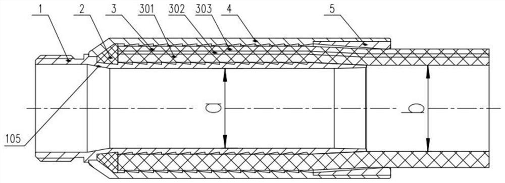
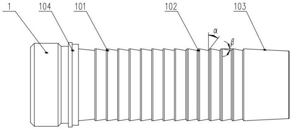
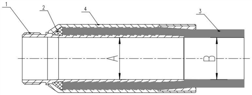
[0031] like Figure 1-5 As shown in the figure, a full-bore high-pressure connection structure of a composite pipe includes a pipe core pipe 1, a vertical tooth profile 101, an oblique tooth profile 102, a conical surface structure 103, a second shoulder 104, an inner cone transition surface 105, and a pipe fitting jacket. 2. Composite tube 3, composite tube inner layer 301, composite tube reinforcing layer 302, composite tube outer layer 303, pipe fitting jacket 4, shoulder 1 401, reinforcing ring 5, tapered surface 501 and arc structure 502.

[0032] The full-bore high-pressure connection structure of the composite pipe is mainly composed of a pipe core tube 1 , a rubber gasket 2 , a composite pipe 3 , a pipe casing 4 and a reinforcing ring 5 .

[0033] The end of the pipe fitting core pipe 1 is provided with a threaded structure (threaded end), which is used to conne...


PUM


Abstract

The invention discloses a composite pipe full-bore high-pressure connecting structure and a connecting structure thereof. The composite pipe full-bore high-pressure connecting structure comprises a pipe fitting core pipe, a pipe fitting outer sleeve arranged on the periphery of the pipe fitting core pipe and a composite pipe arranged between the pipe fitting outer sleeve and the pipe fitting core pipe. A set of outer ring teeth are arranged on the outer surface of the pipe fitting core pipe in the axial direction, a set of inner ring teeth corresponding to the outer ring teeth are arranged on the inner surface of the pipe fitting outer sleeve in the axial direction, a conical surface structure is arranged at one end of the pipe fitting core pipe, and the composite pipe is inserted between the pipe fitting outer sleeve and the pipe fitting core pipe from one end of the conical surface structure of the pipe fitting core pipe. And the section, wrapping the pipe fitting core pipe, of the composite pipe forms a flaring section. According to the connecting structure, only internal expansion is needed, the internal expansion mold is pulled out of the pipe fitting core pipe, the pipe fitting core pipe is expanded outwards, plastic deformation occurs, and internal expansion is completed. Complicated processes such as external buckling are not needed, and connection operation is convenient.

Description

technical field [0001] The invention relates to the technical field of plastic pipe material connection, in particular to a composite pipe full-bore high-pressure connection structure and a connection method. Background technique [0002] Due to its advantages of high pressure resistance and corrosion resistance, plastic composite pipes have been widely used in various industries of the national economy such as petroleum, chemical, natural gas and municipal. At the same time, pipeline connection technology, as a crucial link, severely restricts the scope of use of pipelines. In general, pipeline connection requires that the strength of the connection part should not be lower than the compressive strength of the pipeline body. In the field of oilfield, due to complex working conditions and high working pressure of pipelines, conventional electric melting, hot melting and other pipeline connection methods cannot meet the requirements of use due to their low strength. Therefo...

Claims


Application Information

Patent Timeline
Patent Type & Authority Applications(China)
IPC IPC(8): F16L47/06B29C65/64
CPCF16L47/06B29C65/64B29C66/5221B29C66/034
Inventor 陈江慧陆国强霍福磊叶伟东褚展鹏刘跃明
Owner LINHAI WEIXING NEW BUILDING MATERIALS CO LTD
Why Eureka
Try Eureka