Insulation anti-voltage electric power cabinet
A power cabinet and electric power technology, which is applied in the direction of anti-seismic equipment, substation/power distribution device shell, substation/switchgear cooling/ventilation, etc., can solve the problem of poor compression resistance of power cabinets, easy conduction of power cabinets, and lack of insulation protection devices and other issues, to achieve the effect of easy installation and disassembly
- Summary
- Abstract
- Description
- Claims
- Application Information
AI Technical Summary
Problems solved by technology
Method used
Image
Examples
Embodiment 1
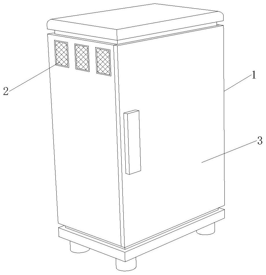
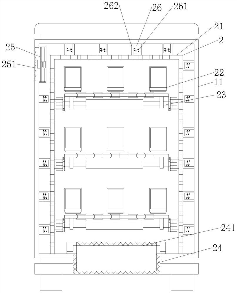
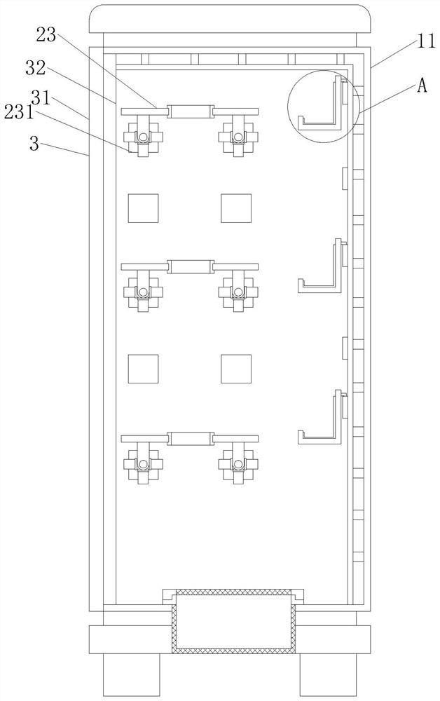
[0030] like Figure 1-6As shown, the present invention provides an insulated and pressure-resistant power cabinet, including a power cabinet body 1, the power cabinet body 1 includes a power cabinet 11, and the inside of the power cabinet 11 is provided with a pressure-resistant internal protection device 2, and the pressure-resistant internal protection device One side of 2 is provided with an insulating protection door device 3 , and the pressure-resistant inner protection device 2 includes a hollow inner protective cover 21 , an electrical component mounting frame 22 and a wire insulation guide plate 23 . The bottom of the inner surface is fixedly connected, the insulating protection door device 3 includes a power cabinet door 31, an insulating protection pad 32 and a central clamping plate 33, one side of the power cabinet door 31 is hinged with the outer surface of the power cabinet 11, and the electrical component mounting frame 22 The outer surface of the card is fixedl...
Embodiment 2
[0033] like Figure 1-6 As shown, on the basis of Embodiment 1, the present invention provides a technical solution: the wire insulation guide plate 23 is arranged on one side of the electrical component mounting frame 22, and the lower surface of the wire insulation guide plate 23 is clamped with an installation support column 232 wire insulation The inside of the guide plate 23 is fixedly installed with an insulated wire conduit 234, and two sides of the installation support column 232 are provided with a clamping block 231. One side surface of the clamping block 231 is fixedly connected to the inner surface of the hollow inner protective cover 21. The clamping block The other side surface of the 231 is fixedly installed with a pressing elastic gasket 2311, the two end side surfaces of the mounting support column 232 are hinged with a clamping claw 2321, and the outer surface of the clamping block 231 is provided with a clamping claw 2321. The two ends of the mounting suppor...
Embodiment 3
[0036] like Figure 1-6 As shown, on the basis of Embodiment 1, the present invention provides a technical solution: the side surface of the central column 2322 is hinged with a tension elastic column 2323, and one end of the tension elastic column 2323 is hinged with the inner surface of the clamping claw 2321, A central extrusion column 233 is provided on the outer surface of the middle of the installation support column 232, and the outer surface of the installation support column 232 is slidably connected with the inner wall of the central extrusion column 233. The middle of the central extrusion column 233 is provided with a folding line rod 2331. The two ends are respectively hinged with the other end of the installation support column 232, the middle part of the folding line rod 2331 is hinged with the extrusion spring column 2332, the bottom of the inner surface of the power cabinet 11 is fixedly installed with the heat dissipation cage 24, and the upper surface of the ...
PUM
 Abstract
Description
Claims
Application Information
 - R&D
- Intellectual Property
- Life Sciences
- Materials
- Tech Scout
- Unparalleled Data Quality
- Higher Quality Content
- 60% Fewer Hallucinations
Browse by: Latest US Patents, China's latest patents, Technical Efficacy Thesaurus, Application Domain, Technology Topic, Popular Technical Reports.
© 2025 PatSnap. All rights reserved.Legal|Privacy policy|Modern Slavery Act Transparency Statement|Sitemap|About US| Contact US: help@patsnap.com


