Phased-array coil, receive sinnal processing circuit, and MRI apparatus

A technology for receiving signal processing and array coils, which is applied in magnetic resonance measurement, fixed signal inductance, and measurement using nuclear magnetic resonance imaging system. It can solve problems such as poor uniformity, achieve high uniform sensitivity and reduce the number of effects.

Inactive Publication Date: 2004-05-12
GE YOKOGAWA MEDICAL SYST LTD
View PDF2 Cites 1 Cited by
  • Summary
  • Abstract
  • Description
  • Claims
  • Application Information

AI Technical Summary

Problems solved by technology

The uniformity of the coil sensitivity characteristics of this traditional phased array coil in the direction of the coil axis is not good
This leads to deficiencies in imaging of the head and lower abdomen where areas of uniform sensitivity are required

Method used


Image

  • Phased-array coil, receive sinnal processing circuit, and MRI apparatus
  • Phased-array coil, receive sinnal processing circuit, and MRI apparatus
  • Phased-array coil, receive sinnal processing circuit, and MRI apparatus

Examples


no. 1 example

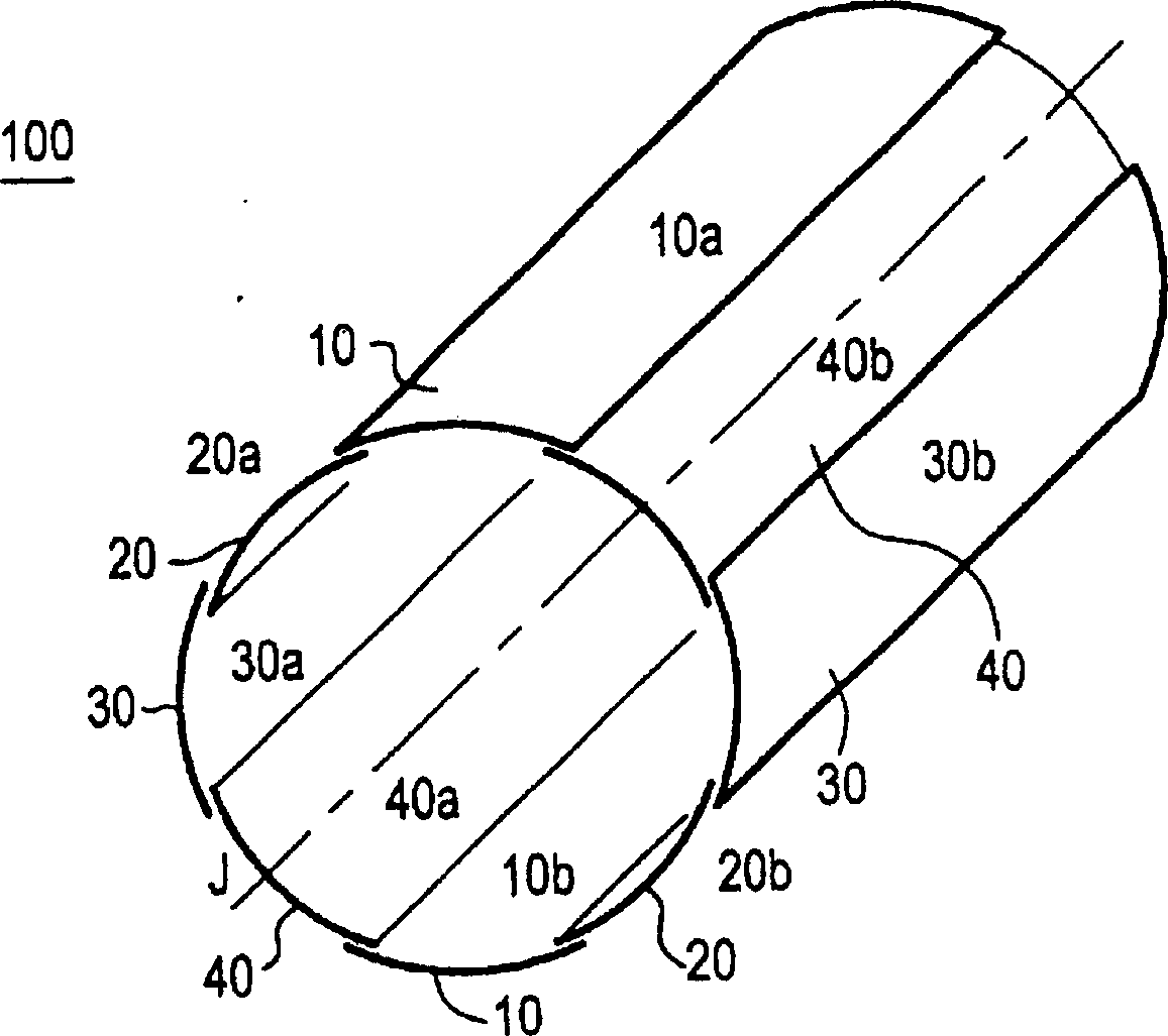
[0038] figure 1 is a schematic perspective view of a cylindrical phased array coil according to a first embodiment of the present invention.

[0039]The cylindrical phased array coil 100 includes: an opposing coil group 10 comprising a pair of slot coils 10a and 10b whose concave surfaces are opposed to each other; The coil group 20; the opposing coil group 30 including a pair of slot-shaped coils 30a and 30b whose concave surfaces are opposed to each other; and the opposing coil group 40 including a pair of slot-shaped coils 40a and 40b whose concave surfaces are opposed to each other ; These opposing coil groups are arranged around the central axis J of the imaginary cylinder so as to be assembled into a substantially cylindrical shape.

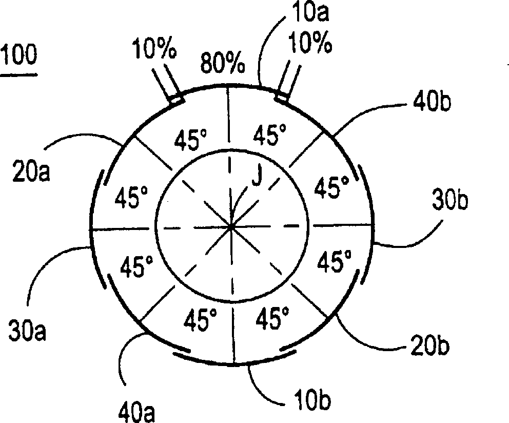
[0040] figure 2 is an explanatory view illustrating the arrangement of opposing coil groups 10 , 20 , 30 and 40 .

[0041] The opposite coil groups (10a, 10b), (20a, 20b), (30a, 30b) and (40a, 40b) are arranged around the central axis J...

no. 2 example

[0057] Figure 7 is a block diagram of a reception signal processing circuit according to a second embodiment of the present invention.

[0058] The received signal processing circuit 1000 includes: low input impedance preamplifiers LA1, LA2, LA3 and LA4 for amplifying the corresponding received signals received at the opposing coil groups 10, 20, 30 and 40 of the phased array coil 100 ; The first quadrature hybrid circuit QH1 is used for quadrature synthesis of the received signals received at the opposite coil groups 10 and 30 separated by 90°; the second quadrature hybrid circuit QH2 is used for the The receiving signals received at the 90° relative coil groups 20 and 40 are subjected to orthogonal synthesis; the first conversion circuit RC1 is used to perform analog-to-digital conversion on the signal that has passed through the first quadrature hybrid circuit QH1; the second conversion circuit RC2, used to perform analog-to-digital conversion on the signal that has passe...

no. 3 example

[0061] Figure 8 is a block diagram illustrating a received signal processing circuit according to a third embodiment of the present invention.

[0062] The received signal processing circuit 2000 includes: a first quadrature hybrid circuit QH1, which is used to perform quadrature synthesis on the received signals received at the opposite coil groups 10 and 30 separated by 90°; the first low-impedance preamplifier LA1 , used to amplify the signal that has passed through the first quadrature hybrid circuit QH1; the first impedance transformation circuit CV1, used to perform impedance transformation between the first quadrature hybrid circuit QH1 and the first low-impedance preamplifier LA1; the first The conversion circuit RC1 is used for frequency conversion and analog-to-digital conversion of the signal that has passed through the first low-impedance preamplifier LA1; the second quadrature hybrid circuit QH2 is used for the opposite coil group 20 and The receiving signal rec...


PUM


Abstract

In order to provide a phased-array coil having a highly homogeneous sensitivity region, an opposing coil set 10 composed of a pair of gutter-shaped coils 10a and 10b whose concave surfaces face each other, an opposing coil set 20 composed of a pair of gutter-shaped coils 20a and 20b whose concave surfaces face each other, an opposing coil set 30 composed of a pair of gutter-shaped coils 30a and 30b whose concave surfaces face each other, and an opposing coil set 40 composed of a pair of gutter-shaped coils 40a and 40b whose concave surfaces face each other are disposed around the center axis J of an imaginary cylinder at an angular spacing of 45 DEG , with each coil overlapping the adjacent ones by about 10% of the coil surface area, to be assembled into a cylindrical shape as a whole.

Description

technical field [0001] The present invention relates to phased array coils and receive signal processing circuits, and more particularly, to phased array coils having highly uniform sensitivity regions and to properly processing receive signals received at such phased array coils. Signal processing circuit. Background technique [0002] National Publication No. 2-500175 of Japanese Patent Application (corresponding to US Patent No. 4,825,162) discloses an example of a phased array coil used in a conventional MRI (Magnetic Resonance Imaging) apparatus in FIG. 4 thereof. The uniformity of the coil sensitivity characteristics in the coil axis direction of this traditional phased array coil is not good. This results in deficiencies in imaging of the head and lower abdomen, which require uniform sensitivity zones. Contents of the invention [0003] It is therefore an object of the present invention to provide a phased array coil having a highly uniform sensitivity region and ...

Claims


Application Information

Patent Timeline
Patent Type & Authority Patents(China)
IPC IPC(8): A61B5/055G01R33/3415G01R33/36
CPCG01R33/3415H01F17/00
Inventor 奈部谷章
Owner GE YOKOGAWA MEDICAL SYST LTD
Why Eureka
Try Eureka