Scanner powered by peripheral bus

A technology of a scanner and a driving circuit, applied in the field of scanners

Inactive Publication Date: 2004-07-28
LITE ON TECH CORP
View PDF1 Cites 0 Cited by
  • Summary
  • Abstract
  • Description
  • Claims
  • Application Information

AI Technical Summary

Problems solved by technology

However, only 2.2 watts

Method used


Image

  • Scanner powered by peripheral bus
  • Scanner powered by peripheral bus
  • Scanner powered by peripheral bus

Examples


Embodiment Construction

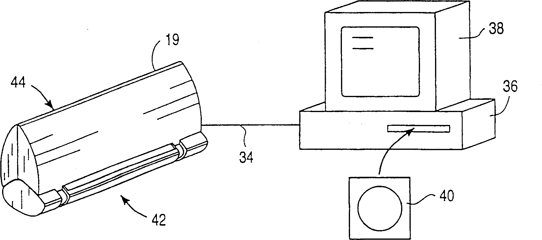
[0022] figure 1 Is a diagram of a computer system including the scanner 19 of the present invention. The scanner is connected to a computer 36 via a bus 34 . Computer 36 includes monitor 38 and is controlled by software on disk 40 . The scanner includes a front end 42 for feeding paper, and a rear end 44 which can also be used for feeding paper, for example with a paper feeder if desired.

[0023] figure 1 Another alternative to the illustrated embodiment is for use with a portable computer (not shown) in which the scanner is built into the portable computer, preferably in front of the portable computer's keyboard. In either embodiment, power may be provided externally or internally to the computer on external bus 34 .

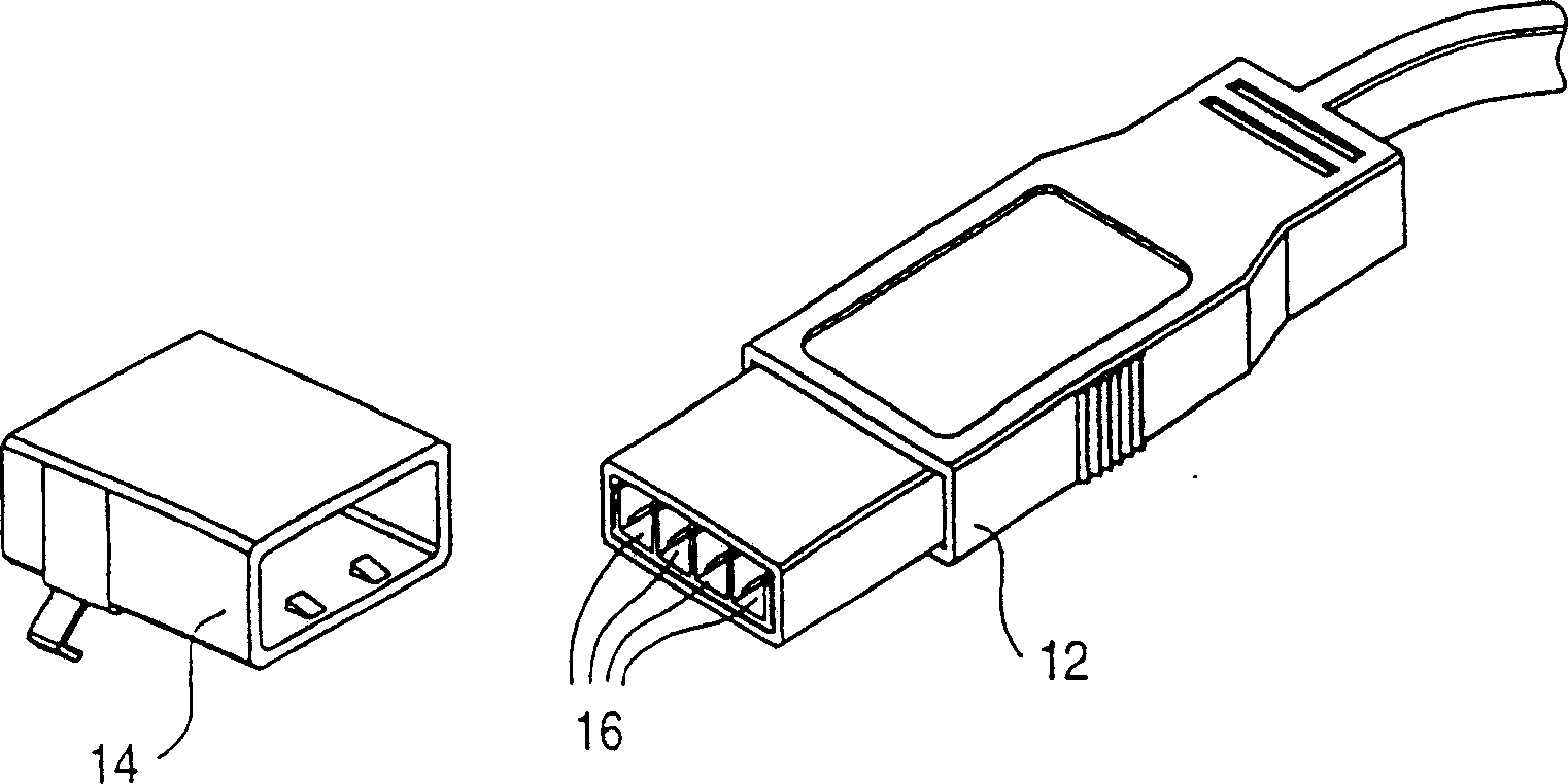
[0024] figure 2 A USB connector comprising components 12 and 14 is shown. As shown, the USB includes four conductors connected to pin 16 . Pin 16 includes two data pins, a power pin and a ground pin. USB is designed to deliver 5 volts and a maximum of...


PUM

PropertyMeasurementUnit
Diameteraaaaaaaaaa
Hardnessaaaaaaaaaa

Abstract

A scanner powered by the limited power available on a peripheral bus. In particular, the scanner can operate within the 2.2 watts provided over a USB connector. The scanner of the present invention uses a contact image sensor (CIS) which uses optics to distribute light from each light emitter to multiple pixel positions, preferably using a single LED for each color. An electric motor for driving the platen uses rare earth magnets to limit the power required. Instead of the traditional method of biasing the CIS scanner against the platen with a spring, the platen itself is spring-biased. The moveable spring biasing of a platen is possible because a worm drive motor is used allowing a helical thread on the worm drive to contact the platen gears as they move up and down as biased. Preferably, the helical thread of the worm gear has a single point of contact with a gear on the platen, further limiting the friction and allowing the platen to move up and down with respect to the stationary motor.

Description

technical field [0001] The invention relates to a page-feeding scanner, in particular to a scanner connected to a host computer by an external bus. Background technique [0002] A typical sheet-fed scanner includes rollers, or platen, that are externally made of a resilient, high coefficient of friction material. The platen is rotated by a motor, pulling the paper into the scanner. The paper typically moves between rollers and a Contact Image Sensor (CIS). A contact image sensor typically includes a row of LEDs, or in color scanners multiple LEDs of different colors. Alternatively fewer or a single LED may be used, with optics spreading the light to all pixel locations in a row. [0003] Such a scanner can also be connected to the external bus of the host computer, or built in a computer, for example a portable computer. A separate power cord is connected to the line power or to the line power in the portable computer to provide the power required to drive the scanner mo...

Claims


Application Information

Patent Timeline
IPC IPC(8): G06T1/00H04N1/00H04N1/04H04N1/12H04N1/193H04N1/48
CPCH04N1/484H04N1/1215H04N1/193
Inventor 约瑟夫·彭扎偌恩戴维·麦克维卡塞尔焦·玛吉戴维·维格穆勒依曼纽尔·罗伊恩斯
Owner LITE ON TECH CORP
Why Eureka
Try Eureka