High-temp mixing valve

A blending valve, high temperature technology, applied in the field of high temperature blending valve, can solve the problems of inconvenient adjustment of high temperature gas flow, inability to meet the requirements of long-term work, and inability to effectively cool down.

Inactive Publication Date: 2004-08-25
CHINA PETROCHEMICAL CORP +1
View PDF0 Cites 6 Cited by
  • Summary
  • Abstract
  • Description
  • Claims
  • Application Information

AI Technical Summary

Problems solved by technology

At present, this kind of blending valve at home and abroad, the material of the valve core of Lurgi company in Germany is made of non-metallic material or metal material, and the head of the valve core is a parabolic structure; the head of the valve core of the French MG company is a bowl-shaped structure bent by steel plate ;The spool of

Method used


Image

  • High-temp mixing valve
  • High-temp mixing valve
  • High-temp mixing valve

Examples


Embodiment Construction

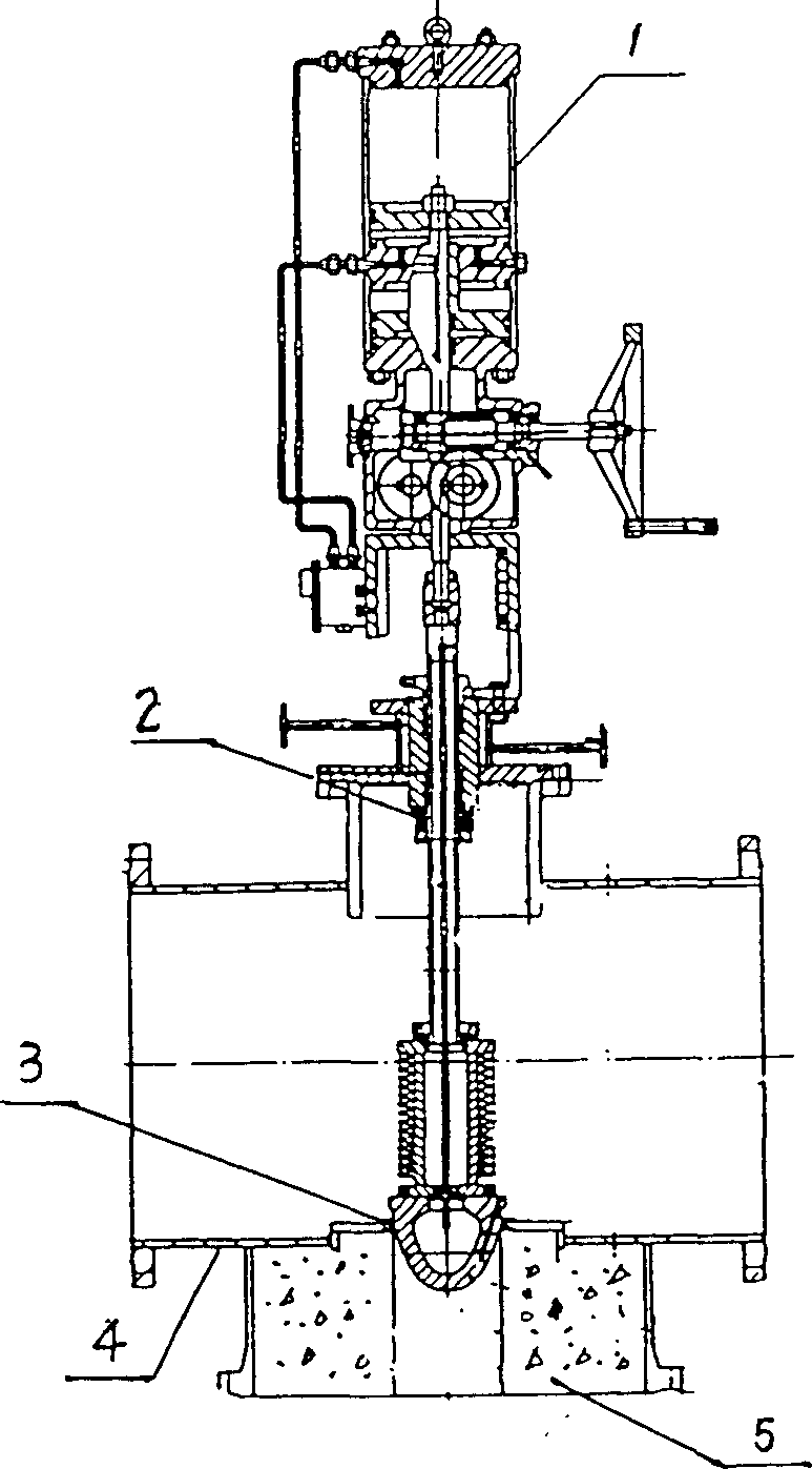
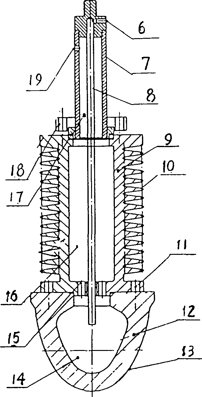
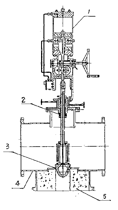
[0019] Figure 1-2 It is the best embodiment of the present invention, wherein: 1 executive mechanism 2 valve stem sealing packing 3 valve seat 4 valve body 5 refractory lining material 6 cooling medium inlet 7 valve stem 8 cooling medium conduit 9 radiator 10 cooling fin 11 valve core, Radiator fastener 12 valve core 13 high temperature resistant and corrosion resistant coating 14 valve core cooling cavity 15 cooling medium return hole 16 radiator cooling medium channel 17 valve stem cooling medium channel 18 valve stem, radiator fastener 19 cooling Media outlet. The high temperature blending valve of the present invention will be further described below in conjunction with the accompanying drawings: Figure 1-2 Shown: The process of making a high-temperature blending valve of the present invention is as follows: After many experiments, the valve core 12 is made of high-temperature-resistant material ZG50 Ni28Cr28W5, and other types of high-temperature-resistant materials ca...


PUM


Abstract

A high-temp mixing valve is composed of valve rod and valve core, and features that the said valve core has the cavity-type parabolic shape. Its advantages include high refractory performance, easily regulating the flow of high-temp gas, simple structure, high cooling efficiency and high regulation sensitivity.

Description

technical field [0001] High temperature blending valve is specially used for high temperature blending. Background technique [0002] The high temperature blending valve is mainly used in the thermal bypass process of the sulfur recovery unit, and can also be used in other high temperature occasions. For example, the sulfur recovery device is an environmental protection device that processes the H2S-containing waste gas discharged from petrochemical enterprises to produce industrial sulfur. When the content and concentration of H2S are high, the reaction furnace burns to produce high-temperature gas at 1200-1400°C, and a part of the gas is mixed with the cold flow medium through the blending valve to provide heat source for the downstream reaction. The blending valve core can withstand the high temperature of 1200-1400°C. At present, this kind of blending valve at home and abroad, the material of the valve core of Lurgi company in Germany is made of non-metallic material or...

Claims


Application Information

Patent Timeline
IPC IPC(8): F16K1/00F16K1/36F16K49/00
Inventor 范西四闵德祥杨荣水王春江葛小平
Owner CHINA PETROCHEMICAL CORP
Why Eureka
Try Eureka