Supercharge Your Innovation With Domain-Expert AI Agents!

Device and method for correcting false contouring in image display system

An image display device and false contour technology, which can be applied to parts of television systems, image communication, image reproducer using solid-state color display devices, etc., and can solve problems such as image quality deterioration and image deterioration.

Inactive Publication Date: 2004-09-22
SAMSUNG ELECTRONICS CO LTD
View PDF17 Cites 0 Cited by
  • Summary
  • Abstract
  • Description
  • Claims
  • Application Information

AI Technical Summary

Problems solved by technology

That is, even when the data value just changes by 1, such as from 127 to 128, if the image changes, the data effect of 225 or 0 is felt at the boundary according to the moving direction of the picture, resulting in a serious deterioration of the image quality
[0006] It has been found that images can be degraded to an undesired degree due to the false contour phenomenon

Method used


Image

  • Device and method for correcting false contouring in image display system
  • Device and method for correcting false contouring in image display system
  • Device and method for correcting false contouring in image display system

Examples


Embodiment Construction

[0028] Although the invention will hereinafter be described in more detail with reference to the accompanying drawings showing preferred embodiments of the invention, it should be understood that this description will enable a person skilled in the art to modify the invention described therein to achieve the beneficial results of the invention . Accordingly, the ensuing description is to be understood as a general guide to a suitably skilled person rather than as a limitation of the present invention.

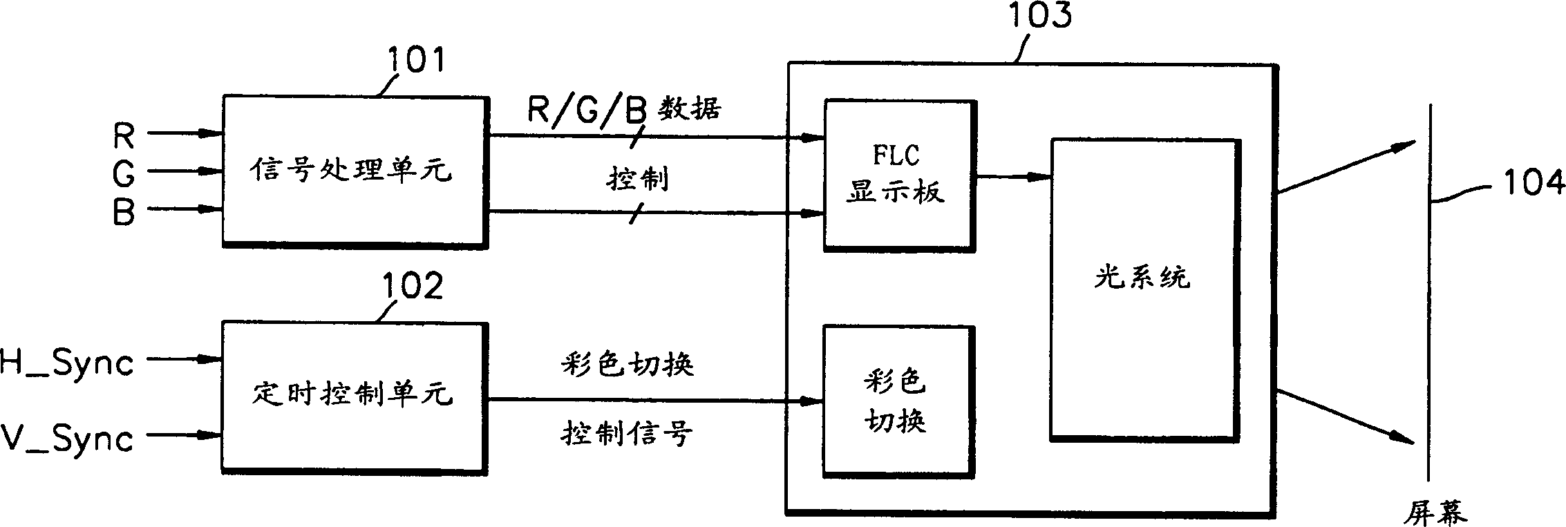
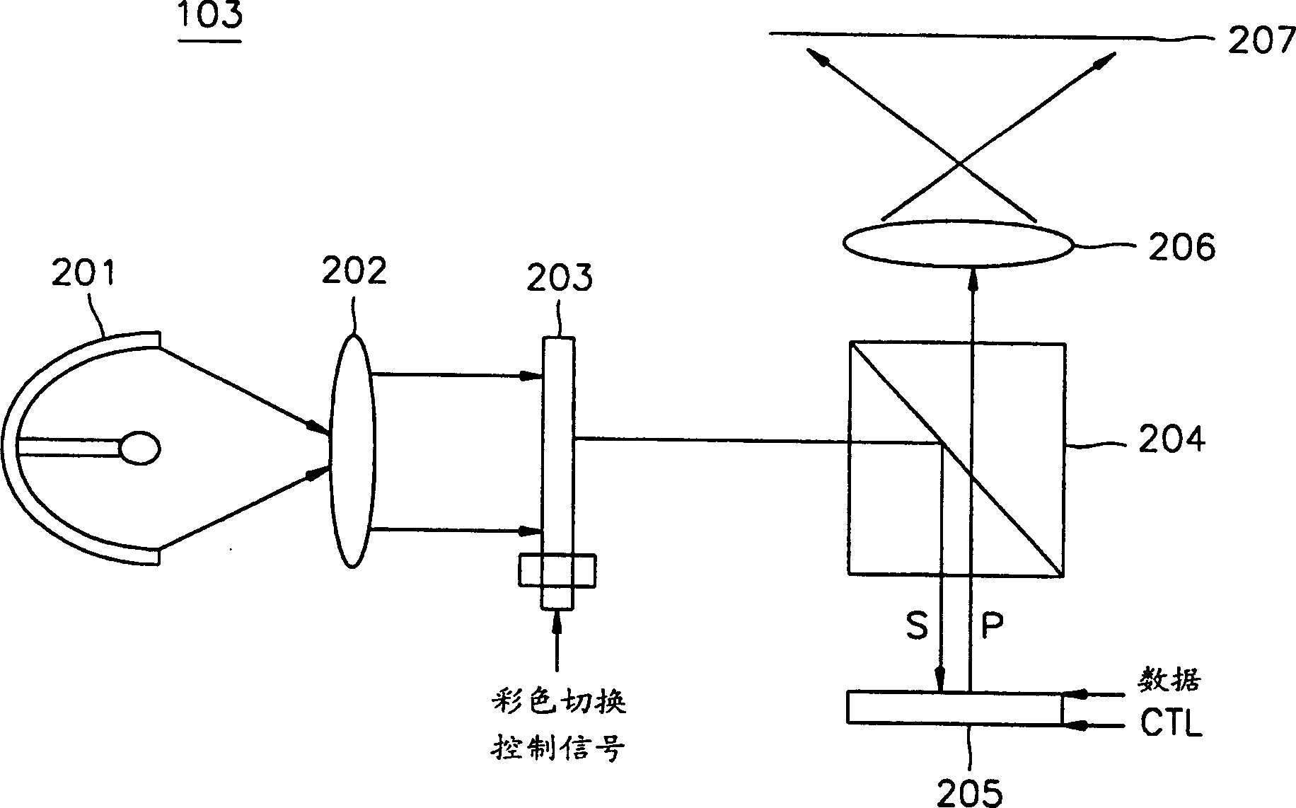
[0029] like figure 1 As shown, the display device using the FLC display panel includes a signal processing unit 101 , a timing control unit 102 , a light engine 103 and a screen 104 . like figure 2 As shown, the light engine 103 includes a light source 201 , a collimating lens 202 , a color switching device 203 , a polarization beam splitter 204 , an FLC display panel 205 and a projection lens 206 .

[0030] The signal processing unit 101 receives R, G, B (red, green, blue)...


PUM


Abstract

A pseudo-contour compensation apparatus and its method in image display system are provided. The apparatus including: A first beam splitter receives a plurality of color light signals, transmits a first wavelength bandwidth and reflects a second wavelength bandwidth. A first panel receives the first wavelength bandwidth of the plurality of color light signals, receives color data and panel control signal, and outputs a first incident light beam according to the panel control signal, to thereby display the received color data in the order of least significant bit starting from most significant bit. A second panel receives the second wavelength bandwidth of the plurality of color light signals, receives the color data and the panel control signal, and outputs a second incident light beam according to the panel control signal, to thereby display the received color data in the order of the most significant bit starting from the least significant bit. According to the present invention as described above, received image data is displayed by reversely-symmetrically arranging the bits of two digital driving display means, so that fatal false contour during digital driving can be removed.

Description

technical field [0001] The present invention relates to an image display device and method, and more particularly to a false contour correction device in an image display system, by which false contours (false contours) where unit bit conversion of data on a display device driven in a digital system is sharp can be corrected. contour). Background technique [0002] Existing types of display devices driven in digital systems include plasma display panels (PDPs), liquid crystal display (LCD) panels, ferroelectric liquid crystal (FLC) panels, and the like. [0003] The FLC display panel has a structure in which a ferroelectric liquid crystal is sandwiched between an optical flat mirror formed on a silicon substrate and glass, and has a wide viewing angle and a fast response speed compared with other display panels. [0004] Image distortion due to an optical illusion in a display device driven in a digital system is called a false contour, and generally occurs where the transi...

Claims


Application Information

Patent Timeline
Patent Type & Authority Patents(China)
IPC IPC(8): G09G3/36G09G3/20H04N5/66H04N5/74H04N9/30
CPCH04N9/30
Inventor 金荣善
Owner SAMSUNG ELECTRONICS CO LTD
Features
  • R&D
  • Intellectual Property
  • Life Sciences
  • Materials
  • Tech Scout
  • Unparalleled Data Quality
  • Higher Quality Content
  • 60% Fewer Hallucinations
Learn More